Summary of OLED Watch Is Alive!
This article details the complete ground-up development of a custom OLED watch, covering electronics design, PCB layout, RTOS firmware, and graphics engines using C, C#, Python, and Altium Designer. The project features USB HID communication, time display, date tracking, accelerometer readings, and debug info. Future plans include Bluetooth 4.0, magnetometer support, smart alarms, and motion-activated screens. The author also describes successful SMD rework to fix broken USB traces by transferring components to a new board and soldering the OLED directly for better fit.
Parts used in the OLED Watch:
- OLED Display
- PCB (Printed Circuit Board)
- USB traces
- Hot-air reflow station
- Spare PCB
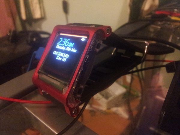
So it’s been a while since I last posted about my OLED watch, and I’ve done a lot of work on it! (And also broke it multiple times)
It’s taken me a lot of work to get this far, and I developed EVERYTHING from the ground up. The electronics design, the PCB layout, the RTOS and firmware drivers, the graphics engine, the user-mode app code, and even USB communications apps. I’ve used C, C#, and Python extensively in this project, and Altium Designer for the schematic and PCB.
Overall it has been an awesome learning experience, and if I was to make another one I would do a lot of things differently!
Here’s a few features of my firmware:
- USB HID Communication (No PC drivers required!)
- Watch face for telling the time (Kind of required…)
- Date & Upcoming events
- Accelerometer reading
- RTOS Kernel debug info
And some features planned for the future:
- Bluetooth 4.0 (Still need to get the IC for it though)
- Magnetometer readings
- Smart alarm clock that wakes me up at the ideal time, by detecting my sleeping patterns through the accelerometer
- Auto screen on by rotating or shaking my wrist
SMD Rework
If you’ve read my last blog post, you’ll know that I ripped the USB traces off my last PCB! I ended up using my hot-air reflow station to transfer the components to a spare PCB, and luckily it all powered up and worked after that! Here are some photos of my reflow process:
Notice how I soldered the OLED directly to the PCB, I had used a connector in my last board but it added extra distance to the OLED cable, so it wouldn’t fit into the case. Soldering directly to the PCB gave me a few more millimeters to work with!
For more detail: OLED Watch Is Alive!
- How was the USB connection issue resolved?
The author used a hot-air reflow station to transfer components from the damaged PCB to a spare one. - Why was the OLED soldered directly to the PCB?
Soldering directly provided extra millimeters of space needed to fit the cable into the case. - What programming languages were used for the firmware?
C, C#, and Python were used extensively for the project. - Does the watch require PC drivers for USB communication?
No, it uses USB HID Communication which requires no PC drivers. - What software was used for schematic and PCB design?
Altium Designer was used for the schematic and PCB layout. - What features are planned for future updates?
Future plans include Bluetooth 4.0, magnetometer readings, a smart alarm clock, and auto screen on via wrist rotation. - Can the watch detect sleeping patterns?
Yes, the planned smart alarm feature intends to detect sleeping patterns using the accelerometer. - What caused the need for an SMD rework?
The USB traces were ripped off during previous attempts, necessitating a rework.