
I hate Christmas tree lights.
Well not really, I just don’t enjoy having to climb under the tree every time I want to plug in or unplug the lights. In the interest of saving my sanity, I decided to build a motion activated switch that can power the lights for me. It has an integrated adjustable timer so they will stay on for as long or as short as I want. Here’s a video showing the final test on the fish tank light.
Step 1: Safety and the parts and tools list
First, a word about safety. We will be working directly with AC mains voltage, so BE EXTREMELY CAREFUL!! Make sure that any time you are testing the circuit, you have your work space clear and anyone around you is aware of the danger. Also, don’t burn yourself with the soldering iron. It is hot. Don’t be that person.
I salvage what I need/want from whatever device I can get my hands on. Most parts are still useful as long as you take care in how you remove them from the original board. That being said, none of the parts are expensive, so it shouldn’t be hard to come across them if need be. Also, many times the exact part is not absolutely required, just something that is compatible, e.g. a 2N2222 NPN BJT instead of the 2N3904 listed.
The Parts:
– 1 power transformer. Any transformer that has a step down factor of 10 will work here. We want an output of about 12-15VAC, but if your outlet supplies 220VAC, it will still work.
– 1 board mounted outlet. You can find these on the back of DVD players, home theater systems, and VCRs.
– 1 rubber grommet. This one came with the AC power cable attached to the transformer and is used to secure the cable to the housing. Very handy if you can get one.
– AC power cable. We don’t need a grounded cable here, so 2 wires will do fine.
– board pins as needed/desired for connecting AC lines. You can also solder directly to the copper pads but it may not be as secure.
– 1 board mounted fuse holder. I used a 5X20mm fuse.
– 1 fuse rated for slightly less than the relay max current rating. Mine is a 250VAC 4A, slow blow.
– 1 555 timer IC with 8-pin socket. Any brand will work.
– 1 7809 +9VDC voltage regulator. You can use whatever regulator you have so long as it matches the DC input rating on your relay switch. You also don’t want a 7909 regulator as it will provide -9VDC, which you don’t want.
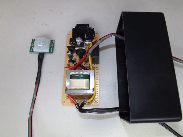
– 1 Parallax PIR sensor. Found mine at radioshack for about $10.
– 1 2N3904 bipolar junction transistor, or BJT. Any NPN BJT should work here.
– 4 1N4001 rectifying diodes. You can also get a bridge rectifier if you want, since that is what we are going to build.
– 3 capacitors: 1 0.01uF (103) ceramic disc; 1 470uF electrolytic; 1 large electrolytic. I used a 1000uF. The large electrolytic will be used to run the timer, so the bigger it is, the longer your max time can be.
– 4 resistors: 2 1k; 1 4.7k; 1 10k
– 1 potentiometer. Mine is a 4 megaOhm pot. This pot will allow for adjusting the timer. With the 1000uF cap, mine will run for about 2.5 hours.
For more detail: Motion Activated AC Switch