
Summary of chipKIT Project 3: Easy Pulse Meter
This article outlines the third project in a chipKIT tutorial series, demonstrating how to build a pulse rate meter. The setup combines an Easy Pulse sensor with a Digilent chipKIT Uno32 board and a Basic I/O Shield to visualize heart rate data on an OLED display. The guide details necessary hardware components, power requirements, and specific SPI interface jumper configurations required to enable communication between the shield and the microcontroller board.
Parts used in the Simple Pulse Rate Meter:
- Easy Pulse sensor
- chipKIT Uno32 board
- chipKIT Basic I/O Shield
- Male/female jumper wires (20 cm long)
- Power supply source (9V DC wall adapter or battery with a clip)
- USB cable
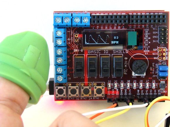
This is a third project in our chipKIT tutorial series and today we are going to construct a simple pulse rate meter using our Easy Pulse sensor with Digilent’s chipKIT Uno32 board. Digilent’s chipKIT Basic I/O shield is also used in this project for displaying the pulse waveform and the pulse rate. – See more at: http://embedded-lab.com/blog/?p=8183#sthash.lA1QV6E3.dpuf
What do we need?
In order to build this project, we will need following things.
- 1 Easy Pulse sensor
- 1 chipKIT Uno32 board
- 1 chipKIT Basic I/O Shield
- 3 male/female jumper wires (20 cm long)
- Power supply source (9V DC wall adapter or battery with a clip)
Besides, a USB cable (not shown in the picture above) is also required to upload the firmware from PC to the Uno32 board.
Where to Buy Easy Pulse Sensor?
International customers buy here
Wire Connections and Setup
The OLED display on the Basic I/O Shield is driven through SPI interface. This requires the JP4 jumper on chipKIT Uno32 board be placed on the RG9 position so that the SPI SS function is available on Pin 10. Read our tutorial Exploring the chipKIT Uno32 for more details on jumper functions and settings on the Uno32 board. The following picture shows the required jumper settings on Uno32 board for this project.
For more detail: chipKIT Project 3: Easy Pulse Meter
- What is the main purpose of this project?
To construct a simple pulse rate meter using an Easy Pulse sensor and a chipKIT Uno32 board. - How is the OLED display driven?
The OLED display on the Basic I/O Shield is driven through the SPI interface. - Where must the JP4 jumper be placed?
The JP4 jumper on the chipKIT Uno32 board must be placed on the RG9 position. - Why is the RG9 jumper setting required?
This setting makes the SPI SS function available on Pin 10 for the display connection. - Can I use a battery as a power source?
Yes, a battery with a clip can be used as the power supply source. - Is a USB cable needed for operation?
A USB cable is required to upload the firmware from the PC to the Uno32 board. - Which board is used for displaying the pulse waveform?
Digilent's chipKIT Basic I/O Shield is used for displaying the pulse waveform and pulse rate. - What length should the jumper wires be?
The project requires male/female jumper wires that are 20 cm long. - Does this project require international shipping options?
Yes, the article provides links for international customers to buy the Easy Pulse sensor.
