
Summary of Building a Constant Current/Constant Power Electronic Load
This project is a beefy constant-current and constant-power electronic load using an Arduino (ATmega328p) and an MCP4921 DAC, built to handle ~200 W using six IRFP150N MOSFETs grouped for balanced dissipation, LM324 op amps for gate driving, and a TL431-based external reference. It supports fine/medium/coarse current adjustment via an encoder and constant-power mode by calculating set current from measured voltage.
Parts used in the Constant Current/Constant Power Electronic Load:
- Arduino (ATmega328p) standard Arduino board
- MCP4921 DAC (Microchip)
- TL431 voltage reference IC
- LM324 quad operational amplifier
- IRFP150N MOSFETs (6 total)
- Gate driving resistors (one per MOSFET)
- Current sense resistor (0.1 ohm mentioned)
- Resistor divider for DAC reference
- Encoder with push button for adjustment
- Large aluminum heatsink (HDD cooler case in earlier design; large aluminum block for this build)
- Filtering and decoupling capacitors (omitted from schematic but used)
A while back I built a simple constant current electronic load using an aluminum HDD cooler case as the heatsink. While it was sufficient for a few amps’ load under low voltages, it could not handle load much higher than a few dozen watts at least not for a prolonged period of time. So this time around, I decided to build a much beefier electronic load so it could be used in more demanding situations.
One of the features a lot of commercial electronic loads has in common is the ability to sink constant power. Constant power would come in handy when measuring battery capacities (Wh) or testing power supplies for instance. To accommodate this, I decided to use an Arduino (ATmega328p) microcontroller.
The schematic below shows this electronic load design. To make the schematic less cluttered, I had deliberately omitted the filtering capacitors and decoupling capacitors. I also omitted the microcontroller circuitry as it is rather standard. All the connections to the standard Arduino board are clearly marked for easy references. The Arduino source code can be downloaded towards the end.
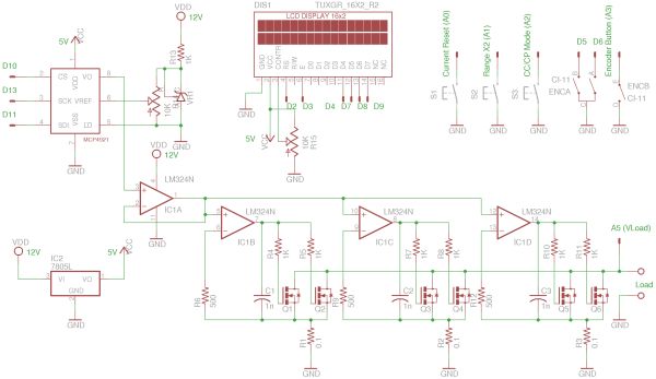
At a first glance, the circuit here seems a lot more complicated than the simple one I built before. But the core power stage portion is actually quite similar.
I used 6 IRFP150N‘s to handle the load. These 6 MOSFETs’ are divided into three groups: each group consists of two MOSFETs paralleled together with independent gate driving resistors. The three pairs are then driven independently via three Op Amps. This design ensures equal distribution of the load current among these three groups of MOSFETs. With this configuration, the maximum power this electronic load can dissipate is at least 200 Watts for a conservative estimate.
In the circuit above, IC1A forms a voltage follower, which buffers the DAC output and the inputs of the three driving Op Amps. An LM324 is used here for the four Op Amps. Of course, the choice of the OpAmps here is not critical and you can substitute with pretty much any general purpose ones. The DAC I used is Mcirochip’s MCP4921. MCP4921 is similar to MCP4821 which I used before. The main difference is that MCP4921 uses an external references whereas MCP4821 has a built-in 2.048V reference. This is also the main reason I chose MCP4921. By varying the external reference voltage, we can strike a balance between the maximum current allowed by the electronic load and the current adjustment resolution.
In my design, the reference voltage to the DAC is provided via a resistor divider from the voltage reference IC TL431. The DAC’s external reference is configured as buffered input for high impedance so that the DAC reference input does not affect the accuracy of the reference voltage set by the resistor divider. When the external reference is set at 0.5V, the load current can be adjusted up to 15A (0.5 V / 0.1 Ohm * 3). MCP4921′s output voltage can be adjusted to upwards to either 1 x Vref or 2 x Vref, so the current range can be doubled via a software command without the need to change the reference voltage. If you do not need such a high current range, you can lower the reference voltage, it will give you a better current resolution (Vref / 4096 per adjustment step).
An encoder is used for current adjustment. By default, the current can be adjusted at a resolution of approximately 1mA/step. By pressing the encoder button, this resolution can be changed to 10mA/step and 100mA/step respectively. This makes it easier to to coarse adjustments.
Constant power mode is achieved by calculating the desired set current via the measured load voltage.
Here are some pictures showing the construction of this electronic load. The heatsink I used is a huge piece of aluminum block I got at a local auction. The original owner builds audio equipment and he used these heatsinks for his class A amplifiers. Anyway, the size of the heatsink is probably an overkill, but it certainly works nicely even without forced air cooling.
For more detail: Building a Constant Current/Constant Power Electronic Load
- What microcontroller is used in this electronic load?
The design uses an Arduino with an ATmega328p microcontroller. - How many MOSFETs are used and how are they arranged?
Six IRFP150N MOSFETs are used, arranged as three independently driven pairs with parallel MOSFETs in each pair. - Which DAC is used and why?
The MCP4921 DAC is used because it accepts an external reference, allowing tradeoff between maximum current and adjustment resolution. - What provides the DAC reference voltage?
The DAC external reference is supplied via a resistor divider from a TL431 voltage reference and buffered before the DAC. - What op amp is used for the gate drivers?
An LM324 quad op amp is used for buffering and driving the MOSFET gates. - How is current adjustment implemented?
An encoder is used; default resolution is about 1 mA per step and pressing the encoder button switches to 10 mA/step and 100 mA/step. - How is constant power mode achieved?
The Arduino calculates the desired set current based on the measured load voltage to maintain constant power. - What current range is possible with a 0.5 V reference?
With Vref = 0.5 V and 0.1 ohm sense resistor, the load current can be adjusted up to 15 A (0.5 V / 0.1 ohm * 3). - Can the current range be doubled without changing the reference voltage?
Yes; MCP4921 can output up to 2 x Vref via a software command to double the current range. - What heatsink was used for this build?
A large aluminum block heatsink (previously the author used an aluminum HDD cooler case for a simpler build).
