Summary of Building a 3-channel, high power RGB LED driver
This article details the construction of a 3-channel RGB LED driver using the PT4115 chipset. The author designed the PCB to learn board design, utilizing beefier components than similar projects like Sparkfun's PicoBuck. The circuit supports up to 30V input and drives 3W to 20W LEDs with adjustable current via sense resistors. PWM control is enabled through solderable headers for use with microcontrollers like Arduino.
Parts used in the 3-Channel RGB LED Driver:
- 3x 22uF tantalum capacitors (C1, C2, C3)
- 3x Schottky diodes 2A SMA package (D1, D2, D3)
- 3x 68uH power inductors rated at 0.7A (L1, L2, L3)
- 3x 0.33ohm resistors in 0805 package (R1, R2, R3)
- 4x 3.5mm screw terminals
- 3x PT4115 drivers
- 1x 4-pin male or female header
- 1x 2-pin male or female header
Hey guys,
I built another board, which is a 3-channel (RGB) LED driver based on an inexpensive chipset called PT4115 (you can find them on eBay or Aliexpress).
The circuit is very simple and looks like Sparkfun’s PicoBuck. However, I used beefier components and a different chip. You may say it’s pretty much the same thing, but I made it to learn some more about PCB design.
Datasheet here. LED current is set through a sense resistor. The output current I is equal to 0.1/Rs. I wanted ~300mA for each channel so I chose a 0.33 ohm resistor. If you want 350mA, choose a 0.27ohm resistor.
Each channel can be controlled via PWM (you can solder male/female headers on the board), for example with an Arduino.
You can input up to 30V and control 3W/10W/20W LEDs.
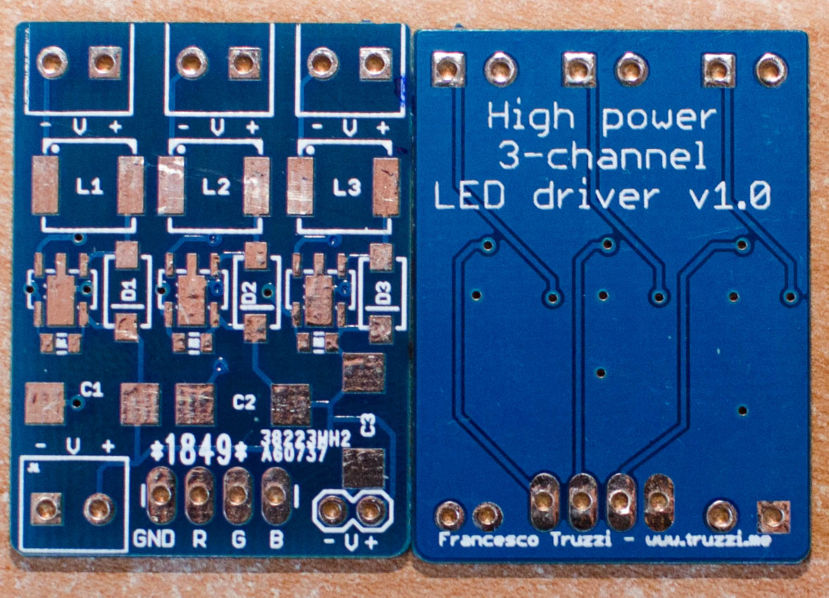
The PCBs.
Needed components:
- C1, C2, C3: 22uF tantalum capacitors (DigiKey part number: 399-3781-1-ND)
- D1, D2, D3; Schottky diode 2A SMA package (DigiKey part number: B240A-FDICT-ND)
- L1, L2, L3: 68uH power inductor, 0.7A (DigiKey part number: PCD2117CT-ND)
- R1, R2, R3: 0.33ohm resistors, 0805 package.
- 4x screw terminals, 3.5mm (bought mine on Tayda Electronics)
- 3x PT4115 drivers.
- 1x 4-pin + 1x 2-pin male or female headers.
For more detail: Building a 3-channel, high power RGB LED driver
- How is the LED output current determined?
The output current equals 0.1 divided by the sense resistor value. - What resistor value sets the current to 300mA?
A 0.33 ohm resistor should be chosen for approximately 300mA per channel. - Can this driver handle inputs above 30V?
No, you can input up to 30V maximum. - How are the channels controlled?
Each channel can be controlled via PWM by soldering male or female headers on the board. - Which microcontroller is suggested for PWM control?
An Arduino is mentioned as an example device to control the driver. - What type of LEDs can this circuit drive?
The circuit controls 3W, 10W, and 20W LEDs. - Where can the PT4115 chipset be purchased?
You can find the PT4115 chipsets on eBay or Aliexpress. - What is the purpose of building this specific board?
The author built it to learn more about PCB design.