
Summary of OhmMeter using Arduino – with Auto Ranging Feature
This article describes an Arduino-based auto-ranging ohmmeter that measures resistance using a voltage divider method and displays results on a 16×2 LCD. It explains that accuracy depends on the input resistor (R1) being close to the unknown resistance (Rx). The system uses an Arduino ADC on channel A5 to measure voltage, calculating resistance based on current flow. To improve precision across different resistance values, the project employs an auto-ranging technique that selects appropriate resistors dynamically.
Parts used in the Auto ranging ohmmeter:
- Arduino microcontroller
- 16×2 LCD display
- Input resistor R1
- Unknown resistance Rx
- Analog-to-Digital Converter (ADC) on channel A5
Auto ranging ohmmeter using arduino.
This article is about a simple auto ranging ohmmeter using arduino. The measured resistance is displayed using a 16×2 LCD display. The circuit is sufficiently accurate and uses minimum number of external components possible. Before going into the details of this project, lets have a look at the basic resistance measurement method.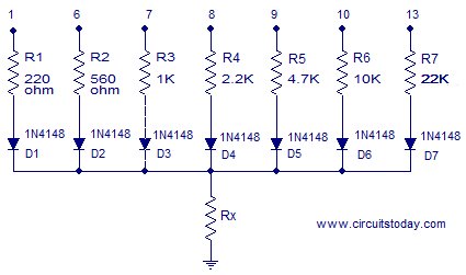
Resistance measurement.
The figure above shows the circuit diagram of a simple resistance measurement scheme. Rx is the resistance to be measured. R1 is the input resistance. i is the current passing through the loop and 5V is the supply voltage. To find the unknown resistance Rx, the voltage across Rx is measured first. let the voltage across R1 be VR1. Then VR1=5-Vx. The current i=VR1/R1=(5-Vx)/R1. Since R1 and Rx are connected in series, the current through them will be equal. So the unknown resistance Rx= Vx/i. The voltage across the unknown resistance is measured using the ADC of the arduino. To be precise, analog channel A5.
Anyway this method have a drawback. If there is great difference between the input resistance and the Rx, the result will be extremely inaccurate. This is because almost all of the input voltage will drop across the larger resistance and this provides very less information.
- Suppose R1=10K and Rx=100 ohm. Then the voltage across R1 will be 4.95v and voltage across Rx will be 50mV and this gives less information. The sensitivity of the arduino is 4.889mV. So when we read 50mV using the arduino ADC the result will be 10. When converted it into voltage the result will be 10 x 4.889mV =48.89mV. Then Rx= 0.0488/((5V-48.89mV)/10000) = 98.7 ohm.
- Suppose R1=10 and Rx=220 ohm. Then the voltage across R1 will be 4.89V and voltage across Rx will be 107mV. The corresponding digital reading will be 21. When we convert it into voltage the result will be 21 x 4.889mV=102mv. Following the calculations used in the previous case, Rx=208 ohm.
In the above two cases you can see accuracy issues. The most accurate result occurs when the Rx and R1 are as close as possible.
Auto ranging.
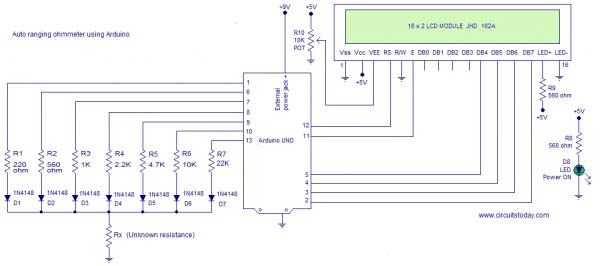
A scheme for estimating the value of Rx roughly and then putting a matching resistor in place of R1 is what we need here and this method is called auto ranging. The circuit given below demonstrates auto ranging.
For more detail: OhmMeter using Arduino – with Auto Ranging Feature
- How is the measured resistance displayed?
The measured resistance is displayed using a 16×2 LCD display. - Which analog channel does the Arduino use for measurement?
The voltage across the unknown resistance is measured using the ADC of the arduino on analog channel A5. - What causes inaccuracy in simple resistance measurement?
Inaccuracy occurs if there is a great difference between the input resistance and the unknown resistance Rx. - When is the most accurate result obtained?
The most accurate result occurs when the unknown resistance Rx and the input resistance R1 are as close as possible. - What is the purpose of the auto-ranging feature?
Auto ranging estimates the value of Rx roughly and then puts a matching resistor in place of R1. - How is the current through the loop calculated?
The current i is calculated as VR1 divided by R1, where VR1 equals 5 minus Vx. - Why does a large voltage drop across one resistor cause issues?
Almost all input voltage dropping across the larger resistance provides very less information for the calculation. - What supply voltage is used in this circuit?
The supply voltage used in the circuit is 5V.
