
Summary of INEFFICIENT NEOPIXEL CONTROL SOLVED WITH HARDWARE HACKERY
This article describes a hardware solution to efficiently control NeoPixels on resource-constrained microcontrollers like the ESP32. The author, Ben Heck, replaces inefficient software-based bit-banging with an external circuit using 7400 series chips. By generating precise timing pulses for NeoPixel data via hardware multi-vibrators and logic gates, this method drastically reduces RAM usage compared to standard library implementations, allowing many more LEDs to be driven with minimal processing power.
Parts used in the Hardware Hackery Project:
- 74HC123 dual multi-vibrator
- AND gate
- OR gate
- External resistor
- External capacitor
Everyone loves NeoPixels. Individually addressable RGB LEDs at a low price. Just attach an Arduino, load the demo code, and enjoy your blinking lights.
But it turns out that demo code isn’t very efficient. [Ben Heck] practically did a spit take when he discovered that the ESP32 sample code for NeoPixels used a uint32 to store each bit of data. This meant 96 bytes of RAM were required for each LED. With 4k of RAM, you can control 42 LEDs. That’s the same amount of RAM that the Apollo Guidance Computer needed to get to the moon!
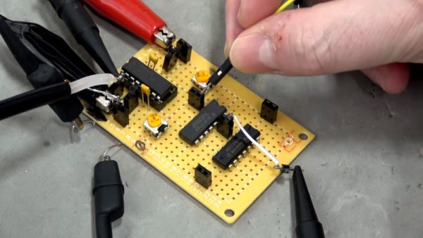
His adventure is based on the thought that you should be able to generate these signals with hardware SPI. First, he takes a look at Adafruit’s DMA-Driven NeoPixel example. While this is far more efficient than the ESP32 demo code, it still requires 3 SPI bits per bit of NeoPixel data. [Ben] eventually provides us with an efficient solution for SPI contro using a couple of 7400 series chips:
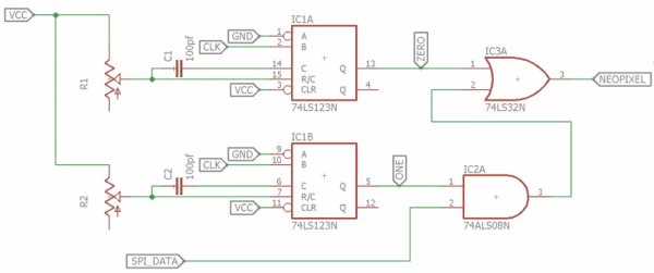
The 74HC123s are clocked by the SPI clock signal, and the SPI data is fed into an AND gate with the long pulse. (In NeoPixel terms, a long pulse is a logical 1.) When the SPI data is 1, the long pulse is passed through to the NeoPixels. Otherwise, only the short pulse is passed through.
This solution only requires a 74HC123, an AND gate, and an OR gate. The total cost is well under a dollar. Anyone looking to drive NeoPixels with a resource-constrained microcontroller might want to give this design a try. It also serves as a reminder that some problems are better solved in hardware instead of software.
Source : INEFFICIENT NEOPIXEL CONTROL SOLVED WITH HARDWARE HACKERY
- Why is the standard ESP32 demo code considered inefficient?
It uses a uint32 to store each bit of data, requiring 96 bytes of RAM per LED. - How many LEDs can be controlled with 4k of RAM using the standard demo code?
Only 42 LEDs can be controlled because of the high RAM requirement per pixel. - What alternative did Adafruit provide that was still not efficient enough?
Adafruit provided a DMA-Driven NeoPixel example that still requires 3 SPI bits per bit of NeoPixel data. - Which chip does Ben Heck use to generate the two pulse lengths needed for NeoPixels?
He uses the 74HC123 dual multi-vibrator. - How are the timing specifications for the multi-vibrators set?
The timing is set by choosing specific external resistors and capacitors. - How does the circuit determine whether to pass a long or short pulse?
An AND gate feeds SPI data into the long pulse; if data is 1 the long pulse passes, otherwise only the short pulse passes. - What is the total cost of the proposed hardware solution?
The total cost is well under a dollar. - What type of signal clocks the 74HC123 chips in this design?
The chips are clocked by the SPI clock signal.
