This is the story of how I made my first robot, and the instructions to build one yourself.
It’s a simple line tracer, controlled by two op-amps. No microcontroller, no programming… simple analog circuitry.
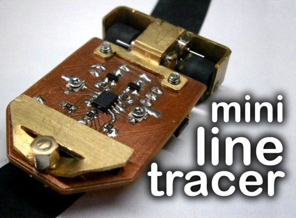
I tried to make it as small as possible, using SMD components and tiny motors.
I’m very happy with the final result, the robot can follow 1-2cm wide black lines on white background, and is quite fast.
It can be made to follow white lines on black background by switching the position of a couple components.
I also made a custom charger because the robot is powered by a 200mAh li-ion battery, you’ll also learn how to make yours.
The circuit works like this:
There’s an IR LED pointing down at the front of the robot, the reflected light is sensed by the two phototransistors, then, the voltage signal is sent to the op-amp and it send more or less current to the motor (through a NPN transistor) depending on the gain, adjusted with the feedback pot.
The design of the circuit is divided into two equal parts, which have the same sensing and driving components.
The robot works in this way:
When it’s on the black line, it advances at an average speed, when the line is curved, one of the phototransistors is out the line, and the other is going into it; the signal from the phototransistor out the line is a higher voltage than before, because it’s resistance has dropped down, then the op-amp sends a bigger signal to the transistor and the motor of it’s side goes faster, turning the robot back into the line.
If you want to make a robot that follows a white line on a black background, you’ll have to switch the position of the phototransistor and the divider resistor, so the phototransistor has the emitter connected to GND and the collector to the resistor and the IN+ of the op-amp.
To make the circuit you’ll need to make the PCB, you can print the PDF below, or order one with the .BRD file.
The components I used are:
-Two 3mm phototransistors (mine from TCRT5000 modules)
-An IR LED
-a 2x and a 3x bent male headers, and a jumper.
-0805 resistors (2x4K7, 2x150ohm, 1x120ohm)
-2x 10K 3mm SMD pot
-2x S8050 SMD transistors
-a MCP602SN dual op-amp (rail to rail)
Step 2: The mechanical part
In the circuit, I left two 3mm holes at the back, so anyone can hook up it’s own mechanical part.
I made mine from a 1mm thick brass plate, in the photos you can see how I cut and bent it. This structure can hold the mini motors and the wheels together and it makes a pretty decent rpm reducer. Then I threaded the holes so I can bolt this structure to the PCB without nuts.
The mini ball roller is used at the front of the robot as an all direction wheel, you can just solder a 5mm LED in that part, it has more friction, but it should work.
With this mechanical design, there are a few problems, the robot turns too fast the front part when there’s a speed change in a motor, resulting in a instable direction, without changing the design, the only solution is making the robot slower, that can be done lowering the gain with the pot. But I realized that a better solution would be to made a different robot design, with the wheels in the same part as the sensors, so the feedback would be much better. But for my first robot, this is OK.
For more detail: Build A Mini Line Tracer Robot Using Arduino