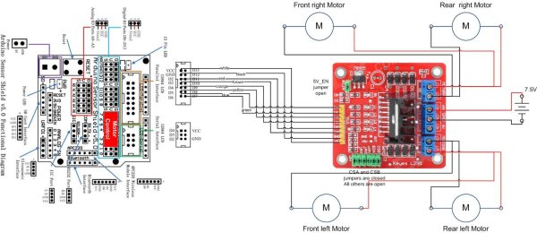
I have created this wiring diagram for the connections between the motor controller, motors, and sensor shield. I’ll update it later to include other components.
And here is an update that includes the servo motor and the range sensor.
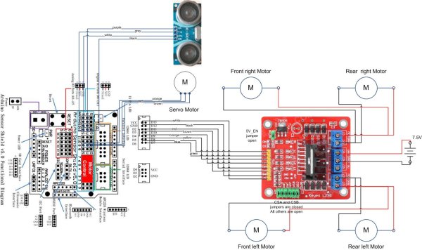
And here are the detailed pin assignments for all modules:
| Arduino Pin | Description | Motor Controller | Range Sensor | Servo Motor | Line Detector | Bluetooth Module |
| VCC | VCC | +5V | VCC | Red | V+ | VCC |
| GND | GND | GND | GND | Brown | G | GND |
| D0 | Digital Pin 0 RX | TXD | ||||
| D1 | Digital Pin 1 TX | RXD | ||||
| D2 | Digital Pin 2 | IN4 | ||||
| D3 | Digital Pin 3 (PWM) | ENB | ||||
| D4 | Digital Pin 4 | IN3 | ||||
| D5 | Digital Pin 5 (PWM) | IN2 | ||||
| D6 | Digital Pin 6 (PWM) | ENA | ||||
| D7 | Digital Pin 7 | IN1 | ||||
| D8 | Digital Pin 8 | S | ||||
| D9 | Digital Pin 9 (PWM) | Orange | ||||
| D10 | Digital Pin 10 (PWM) | |||||
| D11 | Digital Pin 11 (PWM) | |||||
| D12 | Digital Pin 12 | Trig | ||||
| D13 | Digital Pin 13 | Echo | ||||
| A0 | Analog input 0 | |||||
| A1 | Analog input 1 | |||||
| A2 | Analog input 2 | |||||
| A3 | Analog input 3 | |||||
| A4 | Analog input 4 | |||||
| A5 | Analog input 5 |
Disclaimer:
The diagrams above are not the only way you can connect the components so use at your own risk.
For more detail: Arduino robot kit – Wiring Diagram