Being electronics engineers, we consistently rely on meters and instruments to gauge and study the functionality of a circuit. From basic multimeters to advanced power quality analyzers or DSOs, each device serves specific purposes. Many of these gauges are easily accessible and can be bought depending on the measurements needed and their precision. However, there are instances when we may find ourselves in a position requiring us to construct our own meters. For example, if you are involved in a solar PV project and want to determine the power usage of your load, you can create your own Wattmeter using a basic microcontroller system such as Arduino.
Creating your own meters not only reduces testing costs, but also allows for simplification of the testing process. For instance, an Arduino-powered wattmeter can be adjusted to observe the data on the Serial monitor and create a graph on the Serial plotter, or include an SD card to record the voltage, current, and power values at set time intervals. Isn’t that intriguing? Let’s begin now…
Materials Required
- Arduino Nano
- LM358 Op-Amp
- 7805 Voltage regulator
- 16*2 LCD display
- 0.22 ohm 2Watt shunt resistor
- 10k Trimmer pot
- 10k,20k,2.2k,1k Resistors
- 0.1uF Capacitors
- Test Load
- Perf board or breadboard
- Soldering kit (optional)
Circuit Diagram
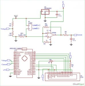
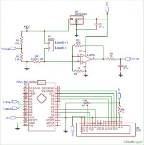
The complete circuit diagram of the arduino wattmeter project is given below.
The arduino wattmeter circuit is divided into two units for easier comprehension. The measuring unit is located at the top of the circuit, while the computation and display unit is situated at the bottom. Those who are unfamiliar with this kind of circuits adhered to the instructions. The label Example +5V indicates that all pins connected to it should be treated as if they are all connected. Labels are commonly utilized to create a tidy appearance in the circuit diagram.
The circuit is created to be compatible with systems that function within a voltage range of 0-24V and a current range of 0-1A, while considering the specifications of a Solar PV. However, once you grasp how the circuit operates, expanding the range is a simple task. The fundamental idea behind the circuit is to monitor the voltage across the load and the current passing through it in order to determine the power it uses. The 16*2 Alphanumeric LCD will show all the measured values.
Let’s divide the circuit into smaller sections to better understand how it is intended to function.
Measuring Unit
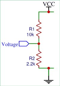
The unit of measurement includes a potential divider for voltage measurement and a shunt resistor with a Non-Inverting Op-amp for current measurement in the circuit. Below is the potential divider segment of the circuit discussed above.
The voltage input, referred to as Vcc, will range from 0V to 24V as previously mentioned. However, an Arduino microcontroller is limited in measuring high voltage, as it can only measure voltage within the range of 0-5V. We need to convert the voltage range of 0-24V to 0-5V. Achieving this is simple with the use of a potential divider circuit depicted below. The combination of a 10k resistor and a 2.2k resistor creates the potential divider circuit. The below formulae can be used to calculate the output voltage of a potential divider. You can utilize our online calculator to determine the value of resistors when redesigning a circuit.
Vout = (Vin × R2) / (R1 + R2)
The Voltage designation indicates where the 0-5V signal is located on the middle section of the map. Later on, this voltage mapping can be inputted into the Analog pin of the Arduino.
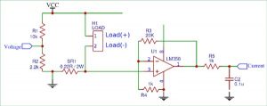
Afterward, we must determine the current flowing through the LOAD. Since microcontrollers are only capable of reading analog voltage, the current value must be converted into voltage for processing. Simply by inserting a resistor (known as a shunt resistor) into the circuit, the voltage drop across it will be directly proportional to the current passing through, as stated by Ohm’s law. We will amplify this small voltage drop using an op-amp because of its low value. Below is the diagram of the circuit mentioned.
The shunt resistor (SR1) has a value of 0.22 Ohms. Earlier, it was mentioned that we are creating the circuit for a load of 0-1A. According to Ohm’s law, we can determine that the voltage drop across the resistor will be approximately 0.2V when the load is drawing up to 1A of current. The voltage is too low for the microcontroller to detect, so an Op-Amp is utilized in Non-Inverting Amplifier configuration to boost the voltage from 0.2V to a level that the Arduino can detect.
The diagram above illustrates the operation of the Op-Amp in Non-Inverting mode. The amplifier’s gain is set at 21 in order to produce an output of 4.2V when multiplied by 0.2. The equation for determining the Op-amp’s gain is provided below, you can also utilize an online gain calculator to ascertain the resistor’s value when modifying the circuit.
Gain = Vout / Vin = 1 + (Rf / Rin)
In this situation, Rf has a value of 20k and Rin has a value of 1k, resulting in a gain of 21. The Op-amp’s increased voltage is passed to an RC filter with a 1k resistor and a 0.1uF capacitor to filter out any coupled noise. Ultimately, the voltage is supplied to the analog pin of the Arduino.
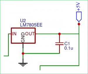
The voltage regulator part is the only remaining section in the measuring unit. As we are providing varying input voltage, a stable +5V voltage is needed for the Arduino and Op-amp to function properly. The 7805 Voltage regulator will supply the regulated voltage. A capacitor is incorporated into the output in order to remove unwanted interference.
Computation and display unit
In the measuring unit we have designed the circuit to convert the Voltage and Current parameters into 0-5V which can be fed to the Arduino Analog pins. Now in this part of the circuit we will connect these voltage signals to Arduino and also interface a 16×2 alphanumeric display to the Arduino so that we can view the results. The circuit for the same is shown below
As you can see the Voltage pin is connected to Analog pin A3 and the current pin is connected to Analog pin A4. The LCD is powered from the +5V from the 7805 and is connected to the digital pins of Arduino to work in 4-bit mode. We have also used a potentiometer (10k) connected to Con pin to vary the contrast of the LCD.
Programming the Arduino
Now that we have a good understanding of the hardware, let us open the Arduino and start programming. The purpose of the code is to read the analog voltage on pin A3 and A4 and calculate the Voltage, Current and Power value and finally display it on the LCD screen. The complete program to do the same is given at the end of the page which can be used as such for the hardware discussed above. Further the code is split into small snippets and explained.
As all programs we begin with, defining the pins that we have used. In out project the A3 and A4 pin is used to measure voltage and current respectively and the digital pins 3,4,8,9,10 and 11 is used for interfacing the LCD with Arduino
int Read_Voltage = A3;
int Read_Current = A4;
const int rs = 3, en = 4, d4 = 8, d5 = 9, d6 = 10, d7 = 11; //Mention the pin number for LCD connection
LiquidCrystal lcd(rs, en, d4, d5, d6, d7);
We also have included a header file called liquid crystal to interface the LCD with Arduino. Then inside the setup function we initialise the LCD display and display an intro text as “Arduino Wattmeter” and wait for two seconds before clearing it. The code for the same is shown below.
void setup() {
lcd.begin(16, 2); //Initialise 16*2 LCD
lcd.print(” Arduino Wattmeter”); //Intro Message line 1
lcd.setCursor(0, 1);
lcd.print(“-Circuitdigest”); //Intro Message line 2
delay(2000);
lcd.clear();
}
Inside the main loop function, we use the analog read function to read the voltage value from the pin A3 and A4. As we know the Arduino ADC output value from 0-1203 since it has a 10-bit ADC. This value has to be then converted to 0-5V which can be done by multiplying with (5/1023). Then again earlier in the hardware we have mapped the actual value of voltage from 0-24V to 0-5V and the actual value of current form 0-1A to 0-5V. So now we have to use a multiplier to revert these values back to actual value. This can be done by multiplying it with a multiplier value. The value of the multiplier can either be calculated theoretically using the formulae provided in hardware section or if you have a known set of voltage and current values you can calculate it practically. I have followed the latter option because it tends to be more accurate in real time. So here the value of multipliers is 6.46 and 0.239. Hence the code looks like below
float Voltage_Value = analogRead(Read_Voltage);
float Current_Value = analogRead(Read_Current);
Voltage_Value = Voltage_Value * (5.0/1023.0) * 6.46;
Current_Value = Current_Value * (5.0/1023.0) * 0.239;
How to measure with more accuracy?
The above way of calculating the value of Actual Voltage and current will work just fine. But suffers from one drawback, that is the relationship between the measured ADC voltage and actual voltage will not be linear hence a single multiplier will not give very accurate results, the same applied for current as well.
So to improve the accuracy we can plot of set of measured ADC values with actual vales using a known set of values and then use that data to plot a graph and derive the multiplier equation using the linear regression method. You can refer the Arduino dB meter in which I have used a similar method.
Finally, once we have calculated the value of actual voltage and actual current through the load, we can calculate the Power using the formulae (P=V*I). Then we display all the three values on the LCD display using the code below.
lcd.setCursor(0, 0);
lcd.print(“V=”); lcd.print(Voltage_Value);
lcd.print(” “);
lcd.print(“I=”);lcd.print(Current_Value);
float Power_Value = Voltage_Value * Current_Value;
lcd.setCursor(0, 1);
lcd.print(“Power=”); lcd.print(Power_Value);
Working and Testing
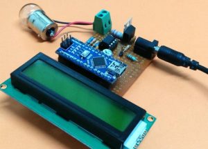
For the sake of tutorial I have used a perf board to solder all the components as shown in the circuit. I have used a Phoenix screw terminal to connect the load and normal DC barrel Jack to connect my power source. The Arduino Nano board and the LCD are mounted on a Female Bergstik so that they can be re-used if required later.
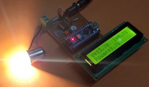
After getting the hardware ready, upload the Arduino code to your Nano board. Adjust the trimmer pot to control the contrast level of the LCD until you see a clear intro text. To test the board connect the load to the screw terminal connector and the source to the Barrel jack. The source voltage should be more than 6V for this project to work, since the Arduino required +5V to operate. IF everything is working fine you should see the value of Voltage across the load and the current through it displayed in the first line of the LCD and the calculated power displayed on the second line of the LCD as shown below.
The fun part of building something lies in testing it to check how far it will work properly. To do that I have used 12V automobile indicator bubs as load and the RPS as source. Since the RPS itself can measure and display the value of current and voltage it will be easy for us to cross check the accuracy and performance of our circuit. And yes, I also used my RPS to calibrate my multiplier value so that I get close to accurate value.
The complete working can be found at the video given at the end of this page. Hope you understood the circuit and program and learnt something useful. If you have any problem in getting this to work post it on the comment section below or write on our forums for more technical help.
This Arduino based Wattmeter project has many more upgrades that can be added to increase the performance to auto data logging, plotting graph, notifying over voltage or over current situations etc. So stay curious and let me know what you would use this for.
/*
* Wattmeter for Solar PV using Arduino
* Dated: 27-7-2018
* Website: www.circuitdigest.com
*
* Power LCD and circuitry from the +5V pin of Arduino whcih is powered via 7805
* LCD RS -> pin 2
* LCD EN -> pin 3
* LCD D4 -> pin 8
* LCD D5 -> pin 9
* LCD D6 -> pin 10
* LCD D7 -> pin 11
* Potetnital divider to measure voltage -> A3
* Op-Amp output to measure current -> A4
*/
#include <LiquidCrystal.h> //Default Arduino LCD Librarey is included
int Read_Voltage = A3;
int Read_Current = A4;
const int rs = 3, en = 4, d4 = 8, d5 = 9, d6 = 10, d7 = 11; //Mention the pin number for LCD connection
LiquidCrystal lcd(rs, en, d4, d5, d6, d7);
void setup() {
lcd.begin(16, 2); //Initialise 16*2 LCD
lcd.print(” Arduino Wattmeter”); //Intro Message line 1
lcd.setCursor(0, 1);
lcd.print(” With Arduino “); //Intro Message line 2
delay(2000);
lcd.clear();
}
void loop() {
float Voltage_Value = analogRead(Read_Voltage);
float Current_Value = analogRead(Read_Current);
Voltage_Value = Voltage_Value * (5.0/1023.0) * 6.46;
Current_Value = Current_Value * (5.0/1023.0) * 0.239;
lcd.setCursor(0, 0);
lcd.print(“V=”); lcd.print(Voltage_Value);
lcd.print(” “);
lcd.print(“I=”);lcd.print(Current_Value);
float Power_Value = Voltage_Value * Current_Value;
lcd.setCursor(0, 1);
lcd.print(“Power=”); lcd.print(Power_Value);
delay(200);
}
Source : Arduino Wattmeter: Measure Voltage, Current and Power Consumption

