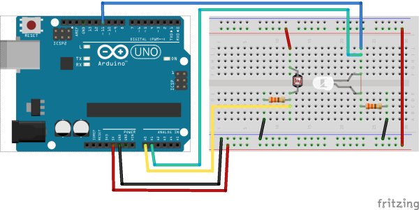
The cmd_response sketch is very general with respect to the ANALOG IN and DIGITAL I/O of the Arduino boards. We can use it to read a wide variety of sensors from remote computer systems.
First, we demonstrate how the Arduino cmd_response sketch works, we construct some simple sensor circuits and then communicate with our Arduino with a Python program (see: Example: Python program sequence.py).
 Later, we integrate the Arduino with EPICS (see: Example: Constant Lighting with EPICS). Finally, we maintain a constant sensor value (photocell) by adjusting an LED’s brightness using a PID loop in EPICS (see: Example: Feedback using the epid record).
photocell
The photocell is a cadmium-sulfide photosensitive resistor. [1] It is an inexpensive device that measures the amount of light reaching its active surface. The resistance of the photocell, R2, changes as the intensity of light changes.
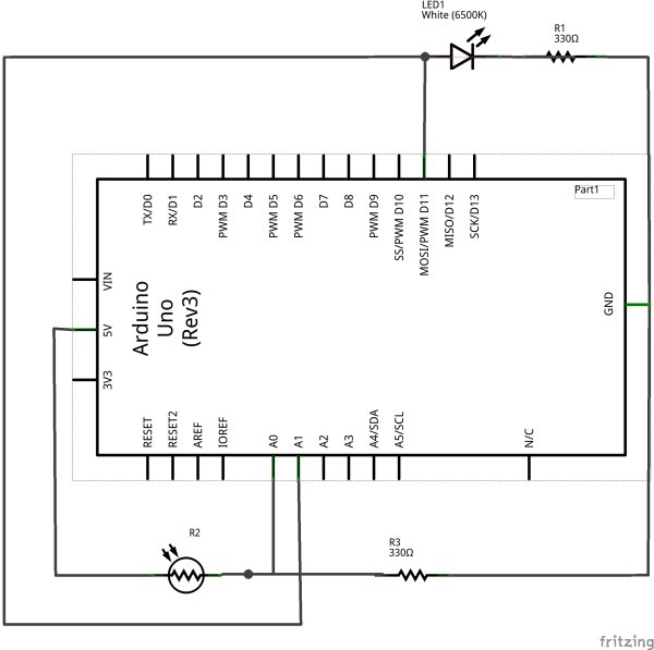
An easy way to sense this resistance is to build a simple voltage divider circuit such as the next figure and measure voltage, VP at the midpoint of the circuit between R2 and R3.
Since the resistance of the photocell, R2, drops with increasing light intensity, we choose to put it closer to the supply voltage, Vcc[2]. As the light intensity increases, VP will increase towards Vcc. The other resistor, R3, is chosen to limit the maximum current through the divider as R2 tends towards zero.
Voltage divider circuit with the photocell (photocell-schem.png)
| connection: | We’ll connect VP to ANALOG IN channel A0. |
|---|
| [1] | photocell: http://en.wikipedia.org/wiki/Photoresistor |
| [2] | Take Vcc from the Arduino’s 5 VDC supply. |
 LED
LED
The LED is an inexpensive device that generates light when a current is passed through it. A resistor is used to limit the current which flows through the LED as it is driven from one of the DIGITAL pins on the Arduino. Arduino has an example to vary the intensity of the LED using pulse-width modulation and the analogWrite() function. [3]
For more detail: Electronic Circuit photocell and LED

