Overview
As avid audiophiles, we wanted to apply our newly acquired knowledge of microcontrollers to build a fun consumer electronic device. Our project is a step sequencer drum machine. The user is able to program a 16-step percussion pattern using one of a wide range of percussion instruments on each of six different tracks. The user toggles between different tracks and different instruments and adjusts tempo through an intuitive user interface consisting of pushbuttons and an LCD display. Configurations can also be saved and loaded from the microcontroller’s EEPROM.
High Level Design
Rationale & Inspiration
Wikipedia writes: “A drum machine is an electronic musical instrument designed to imitate the sound of drums or other percussion instruments. They are used in a variety of musical genres, not just purely electronic music. They are also a common necessity when session drummers are not available or desired.”
It is common today for drum machines to be purely software devices. Our device is a throwback to 15-20 years ago when hardware drum machines were common. Such hardware drum machines were large, expensive, and clumsy devices. Our device is a modern take on the hardware drum machine. It is inexpensive and features an intuitive and simple user interface.
Our rationale for embarking on this project was to create a fun and interesting electronic musical instrument that could provide enjoyment to even non-musically inclined individuals. In addition to being a fun device, our drum machine could have practical uses. It could be used to complement a solo performance, or as a means of composing electronic music.
We were inspired by the Rhythm Ring, a Spring 2008 ECE 4760 final project by Brian Yung & Hanson Jiang. While we liked the sequencer idea of the Rhythm Ring, we wanted to improve the user interface to mimic an industry standard drum machine which offers a greater amount of control on the number of tracks and instruments to play back, the speed at which to run the sequencer, and the ability to save and load user generated patterns. While searching online, we found a more sophisticated drum machine that we really liked named the Beat707 which is Arduino-based. We based our user interface on their pushbutton and sequencer LED design which was more in sync with industry standard drum machines.
Concept
We set out to create a drum machine in the spirit of the hardware step sequencer drum machines that were prevalent 15-20 years ago and that still exist today. The programming interface is a row or grid of 16 pushbuttons—representing a 16-step musical bar. The user places sounds by pressing the pushbuttons and the created pattern is played back as a sequencer loops through the 16 steps.
In our design we include just one row of pushbuttons. The user programs one of six possible tracks (voices) at a time. LEDs above each step indicate which steps are currently selected. The LEDs also indicate the progress of the sequencer—lighting at the current step if it is not selected in the pattern and turning off it it is (XOR with the pattern).
A control panel of an LCD and up/down/left/right pushbuttons allows the user to change the currently selected track, select instruments for each track, adjust the tempo of the sequencer, and save/load preset configurations. A total of 20 different instruments are available—including typical percussion instruments (bass drums, snare drums, hi-hats, etc.) as well as some more electronic sounds. The tempo can range between 60 and 220 beats per minute (BPM). The user can save up to 50 preset configurations—which are stored in the MCU’s EEPROM and therefore preserved even when the power is off.
Three additional pushbuttons allow the user to play/pause the sequencer, clear the currently selected track, or clear the entire configuration (the patterns and instruments for all six tracks as well as the tempo) and return it to the default.
Our device plays back digitally sampled sounds at 22,068 Hz stored in the MCU’s memory. Audio playback is through a digital-to-analog converter (DAC) and fed to a 3.5mm mono audio jack that is designed to be connected to high-impedance computer speakers.
Logical Structure
Logically the MCU must perform two primary tasks: audio playback and user interface processing.
As mentioned earlier, audio playback is accomplished by having the MCU output audio samples to a DAC. The interface between the two is the Serial Peripheral Interface (SPI) and the samples are output from an interrupt service routine (ISR) running on the MCU in order to maintain accurate output at the desired sampling frequency (22,068 Hz).
User interface processing is a significant task and requires the majority of the hardware and software. In order to reduce the number of I/O pins required, the 23 pushbuttons and 16 LEDs are connected to shift registers and read/driven serially by the MCU. Note there is no hardware connection between the pushbuttons and LEDs—pushbutton input is processed and output to LEDs all in software.
Hardware/Software Tradeoffs
During the planning stages of this project, we made several high level hardware related decisions. In order to play back audio samples, we decided to use a hardware digital to analog convertor (DAC) rather than software pulse width modulation (PWM). We did this primarily to simplify the software and also because we believed it would improve the overall audio quality.
Another hardware decision we had to make was the size of our LED and pushbutton arrays. Early on we considered using a 16×4 array of LEDs and pushbuttons (one row for each of four possible tracks) and an additional row of 16 LEDs that would show the progress of the sequencer. We quickly realized that this would result in too many wires and connections and the hardware would become unnecessarily complex. Instead we chose to reduce the hardware complexity by using just a single row of 16 LEDs and pushbuttons. Track switching is handled in software. We also merged the sequencer LEDs and pushbuttons LEDs into one single row of LEDs. The sequencer XORs with the pattern as it progress through. This change freed us from being limited to only four tracks by the hardware. Now a change in the software could increase the number of tracks. We decided to implement six tracks in our final device—our original concept contained just four.
We also traded off hardware in favor of software in the design of the control mechanism. Initially, we planned on using dedicated pushbuttons for changing the track and selecting instruments, and a potentiometer for adjusting the tempo. We realized that this would have led to a very cluttered user interface and would lead to challenges if we wanted to implement more complex control functions like the saving/loading of presets. Instead we designed an interactive LCD display showing the currently selected track, instrument and tempo. The LCD also contains a menu option to save/load presets. The user navigates the display and makes changes using up/down/left/right control buttons. The input is all processed in software via state machine. The result is an elegant and easy-to-use user interface.
Standards
We made use of the SPI standard in order to communicate between our MCU and DAC. An additional standard relevant to our design is the IEC 825-1 (International Electromechanical Commission) “Eye Safety Classification of Some Consumer Products” which sets the standard for LED and laser brightness to keep the users’ eyes safe from unsafe levels. We met this standard by refraining from using super-bright LEDs and we set the spacing between LEDs keeping this standard in mind.
Existing Patents, Trademarks, & Copyrights
By conducting a non-exhaustive patent search through the Google Patent search engine, we found several patents for music sequencers and rhythm synthesizers. Although these designs use similar ideas of synthesizing prerecorded sounds, they do not share the same user interface or use the same method of using pushbuttons to create a pattern with control over every step. However, since our idea for the drum machine and synthesizer is borrowed from that of commercial synthesizers, there must exist a patent for such a device even though it might have expired by having been filed more than twenty years ago.
We based much of our design on the Beat707 MIDI drum machine produced by Rugged Circuits. Although we did not use any of their code, we were inspired by the way they implemented the drum machine and a sequencer. The Beat707 is still under open-source development and not yet commercially available; there has been no formal patent filed.
We recognize that since our device is not entirely novel, it does not have any patenting or publishing potential. We did not create this device for commercial purposes but rather to apply our knowledge of microcontroller programming to create an interesting device for educational purposes. We do not plan to file a patent for our device nor do we wish to infringe any patents that may have been previously granted to another party. We do not believe that we are infringing anybody’s trademarks or copyrights by titling our project the ‘Step Sequencer Drum Machine’ as a brief Google search did not yield any hits on this particular title.
Hardware Design
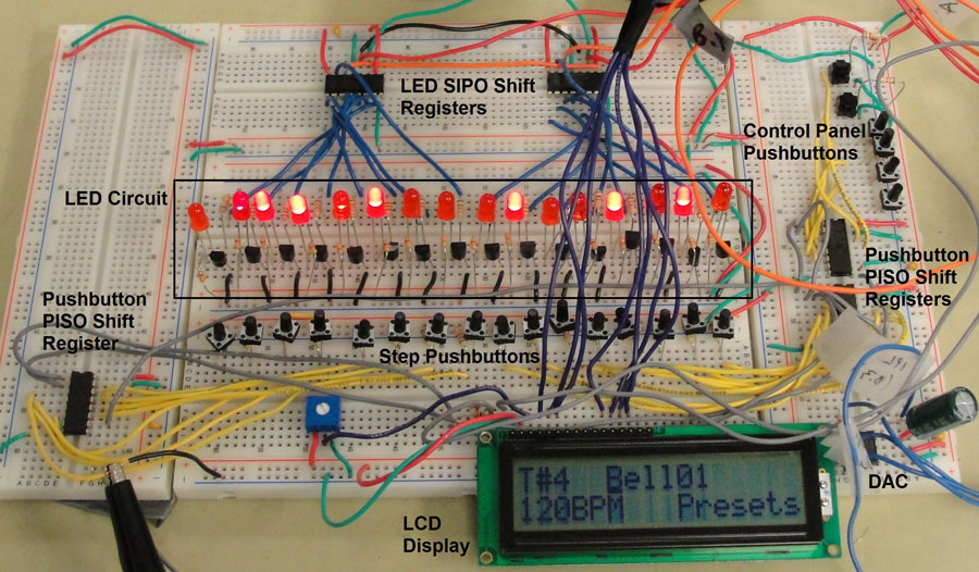
Because of the elaborate user interface this project involves a significant amount of hardware. For this reason we approached the hardware design in two phases: a prototype stage and the final assembly. During the prototyping stage, we constructed the entire device on solderless breadboards. Such a prototyping phase allowed us to realize the most efficient wiring schemes and also gave us flexibility to change our design as the software required. It also allowed for easy accessibility to various nodes in our circuit during debugging.
To house the Mega644 MCU we used the ECE 4760 custom PCB target board designed by Professor Bruce Land. It contains the microcontroller along with all the necessary power and auxillary circuitry. We power the target board with a 9V battery, and use the MCU’s 5V Vcc to power all our other circuitry.
In addition to the target board our device contains 3 primary subcircuits: the pushbutton circuit, the LED circuit, and the DAC circuit.
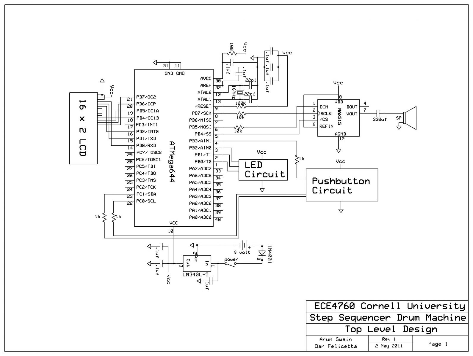
As described earlier, our device contains 23 pushbuttons. Instead of connecting all 23 pushbuttons to individual pins on the Mega644—which would have caused a shortage of pins for our other components—we connect them to three cascaded 74HC165 8-bit parallel-in-serial-out (PISO) shift registers.
Each 74HC165 contains 8 parallel inputs (D0-D7). These pins are pulled-up to Vcc through a 10 kOhm resistor (to limit the current to the pin) and the pushbutton is connected in a shunt branch to ground. We selected pushbuttons with no bounce. The result is a logic low pulse on the input when the pushbutton is depressed. The 74HC165 loads the input pin values into an internal register when triggered to do so by a logic low pulse on the parallel load pin (1). It then shifts the contents of the register out serially on the output pin (9) when triggered by the clock pin (2). The Mega644 provides the parallel load and clock signals and receives the serial data output (Q7) as input.
For more detail: Arduino Step Sequencer Drum Machine