Do not attempt this project if you are not comfortable working with line voltages! ***
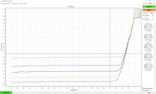
This projects shows how to create an IV (Current and Voltage) Tracer that can be used to teach the electrical characteristics of a solar panel.
This project was created as part of an Electrical and Computer Engineering capstone project at The Ohio State University.
Step 1: What We Used for This Project
Tools:
- Drill
- Drill Bits
- Philips Screwdriver
- Soldering Iron
- Wire strippers
- Needle Nosed Pliers
- Banana Jack Test Leads
Parts:
See the parts list for a complete list as well as links for all the parts.
Step 2: Order Your Circuit Board.
We used Advanced Circuits for our circuit board, but you are welcome to use any PCB shop you like.
If you do not already have Eagle Cad installed on your computer, use the link below to install the free version.
http://www.cadsoftusa.com/download-eagle/?CMP=KNC-GUS-FUS-GEN-SUP-CAD-Eeagle-CAD
Step 3: Drill Holes for the Power Supply.
Using the bottom of the power supply as a templet, drill 4 holes large enough for the M4 machine screws though the bottom on the hefty shoe box.
Step 4: Mount the Arduino Uno.
Using a Philips head screw driver, remove the top honeycomb cover from the power supply. Mount 4 of the M3 PCB spacers on the honeycomb using M4 washers to prevent the nylon spacer nuts from slipping through the honeycomb. Then use another set of spacers to secure the Arduino to the power supply cover. Take care to ensure the Arduino is not contacting the metal cover as this may cause a short circuit.
Step 5: Solder the Components to the PCB.
- Using the included schematic as a guide, soldered the op-amps, resistors, capacitors, wires, and the DAC to the board.
- Coat the back of both op-amps with an even coverage of thermal compound taking care not to get the compound on the op-amp pins.
- Position the heatsinks behind both op-amp, and use some extra PCB spacers to secure the heatsinks to the op-amps.
- Solder the pins of the heatsinks to the board. Be patient as it will take a large amount of heat to bring the pins up to the right temperature for the solder to melt.
Read more: Create A Solar Cell IV Curve Tracer