Here is how to connect a motor, a switch and an LED to your Arduino and how to do some checking to make sure that everything works.
The strategy is to get the circuit going in stages, testing each part as you go. Once everything is wired correctly and can be either controlled or read by the computer correctly, then you can write the main program with confidence that all the pieces are working.
LED
Follow the directions shown in the Arduino Guide (PDF file) under the “Flashing an LED” section. Use this program to confirm that the LED works under computer control
pinMode(2,OUTPUT);
digitalWrite(2,HIGH);
delay(1000);
digitalWrite(2,LOW);
The LED should go on for 1 second.
Switch
Here is how to wire up a membrane switch.
Follow the directions shown in the Arduino Guide under “Reading a Switch”. Use the program shown in the Guide to confirm that the Arduino is reading the switch properly. The stream of 1’s going across the monitor window should change to 0’s when you close the switch. If it doesn’t, read the voltage at Pin 3 with your DMM. It should be 5 V with the switch open and 0 V with the switch closed. If it isn’t, remove the switch from the circuit and check for continuity with the beeper function of your DMM. The DMM should beep when the switch is closed (short circuit) and stay silent when open (open circuit). Sometimes switch contacts get dirty so if you aren’t getting a short circuit, try wiggling the switch button while it is closed. The code assumes the switch is connected to Pin 3 on the Arduino, but any pin can be used.
Motor
Do not connect your motor directly to an Arduino pin and do not use the 5 V power from the Arduino board to power your motor. Instead, control the motor using your TIP120 transistor and a separate 9V or 12V battery. The motor can be either the gear motor or the small motor. For the small motor, you can use the 2N3904 transistor as the switch.
The TIP120 transistor pins look like this.
Here is the schematic diagram for how to connect the motor
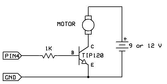
“Px” is any I/O pin on your Arduino. For this exercise, use P4. Connect the minus of the battery to the emmiter of the transistor (E pin) and then also connect the emmiter of the transistor to GND on the Arduino board. Check these connections carefully because you never want the plus of the battery to directly connect to an Arduino pin.
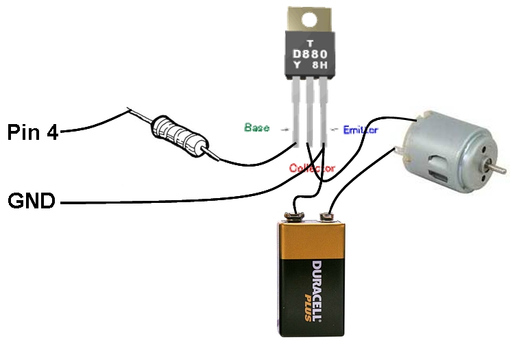
Here is a pictorial diagram of the connections. Connections should be made on the solderless breadboard rather than by soldering.
For more detail: MOTOR SWITCH LED Using Arduino