I’ve found several sites and posts explaining how to use a quadrature encoder with an Arduino, but wasn’t completely satisfied with any of the methods used. Perhaps part of the problem is with the encoder I’m using: it’s part #COM-09117 at Sparkfun.com.
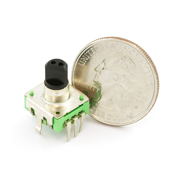
This encoder has twelve detents per rotation, and each detent covers one complete cycle of Gray code. This means that the most common method of reading the knob counts four steps per detent, which isn’t what I wanted.
So, backing up a bit… Here’s how one of these things works. Instead of separate pins for each position as the knob turns, there are two pins (A and B) that produce offset pulses. The direction of the offset indicates the direction of the rotation.
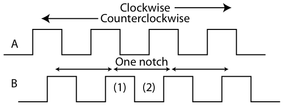
As you can see from the diagram, as you rotate the knob clockwise, the pulses from A lead the pulses from B. Rotating counterclockwise, the pulses from B come first.
The detent spacing is marked on the diagram as “one notch”, and if you just keep track of changes on A and B there are four steps between detent positions. There is an event that happens only once per detent, though: that is a falling (or rising) edge on either A or B. So what I did is run an interrupt on the falling edge of A. Clockwise, B is high when A has its falling edge (at point 1) and counterclockwise B is low when A has its falling edge (at point 2). The interrupt routine just reads B, and adjusts the recorded position of the knob accordingly.
I connected one quadrature pin to Arduino pin 2 and the other to Arduino pin 3. Pin 2 is interrupt 0 for the Arduino. Here’s my code:
/* knobtest.pde
Test of optical encoder (Gray scale)
Eric Ayars
*/

byte Blinker = 13;
int Delay = 250;
byte A = 2;        // One quadrature pin
byte B = 3;        // the other quadrature pin
volatile int Rotor = 0;

void setup() {

// set DIO pins
pinMode(Blinker, OUTPUT);
pinMode(A, INPUT);
pinMode(B, INPUT);

// Turn on pullup resistors
digitalWrite(A, HIGH);
digitalWrite(B, HIGH);

// Attach interrupt to pin A
attachInterrupt(0, UpdateRotation, FALLING);

// Use serial port to keep user informed of rotation
Serial.begin(9600);
}

void loop() {
// Basic blink program here: interrupt comes in as needed.
digitalWrite(Blinker, HIGH);
delay(Delay);
digitalWrite(Blinker, LOW);
delay(Delay);
}
For more detail: À l'aide d'un encodeur en quadrature (commutateur rotatif) avec Arduino