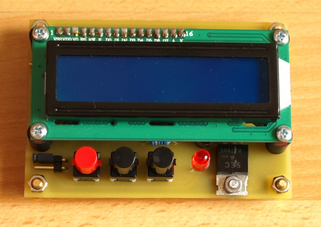
This is a quick project for a timer. Recently I finished my UV light exposure box and thought that it will be convenient to have a build in timer to switch off the light after preset time. So I had a PIC16F628A lying around and after searching the web I found a Brazilian site (I think?) with tons of interesting projects with microcontrolers. This project is based on one of them.
There are three buttons to operate the timer: “START/STOP”, “MIN” and “SEC”. “START/STOP” is for starting and pausing the timer. “MIN” is for adjusting the minutes. Minutes may go up to 99 and then starts again from 0. “SEC” is for adjusting the seconds. Seconds goes up to 59 and then starts from 0. “MIN” and “SEC” have repeat functionality. Pressing MIN and SEC buttons simultaneously will reset the timer. When the timer reach 00:00, the buzzer sounds 3 short and 1 long beeps and the LED lights up. The buzzer is electromagnetic type.
After this any of these three buttons will reset the status and LED will switch off. When timer is counting down – RB7 (pin 13) is high and when the timer is stopped – RB7 is low.
With this pin we can operate some external circuitry. In my case there will be connected a transistor which will switch on and off the UV exposure box.
Jumper J1 is for calibrating of the timer. When shorted, the timer enter in adjusting mode. With MIN and SEC buttons we can increase/decrease the value of an internal parameter thus slowing down or speeding up the timer. This value is stored in the EEPROM. Pressing START/STOP button when in this mode will reset this parameter to its default value.
I tested the schematic on the breadboard and everything works as described.
The code is written and compiled with mikroC PRO for PIC. The options for the project are:
- Oscillator: INTOSC oscillator: I/O function…
- Oscillator frequency: 4.000000 MHz
- Watchdog Timer: disabled
- Power-up Timer: enabled
- RA5/MCLR/VPP pin function: disabled
- Brown-out detect: enabled
The .hex file was programmed in the microcontroller with my clone of PICkit2 using “PICkit 2 programmer” v.2.61
Link for downloading the schematic, source .c file and .hex file: Timer (PIC16F628A)
For more detail: Simple timer with PIC16F628A

