I’m going to show you how to use your Arduino to control up to 12 servos at once with minimal jitter. Using a simple serial interface you can control the position of up to 12 servo channels. Up to 10 snapshot positions can be saved and played back at any time. Start up values for each servo can be saved as well.
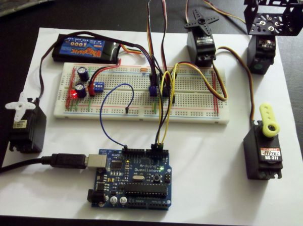
There are two major parts to the application. The first part I will discuss is the firmware and hardware. This includes the Arduino and another board we will use to supply power to the servos. It’s important to isolate the servo power supply from the microprocessor power in case the servos need more current than the battery can supply (imagine all 12 servos stalling at once). If the power supplies are the same you could have a brownout condition on your microprocessor depending what type of power supply you are using. I will also show you the firmware required to run this application on the Arduino.
In the second part I will discuss some simple software that will allow you to control the firmware through serial commands. This software provides an interface to the Arduino firmware to control the servos, save servo start up positions, even record a series of positions, or frames, (of all channels saved at once) to playback in sequence when desired. The software is .Net based so make sure you have the latest .Net framework installed. I will be supplying an installer and source code.
Step 1: Parts List
The following is a list of material and items I used for this instructable:
1x Arduino Board (Any variant that has a 328p processor)
1x BreadBoard
1x Battery 6.0-8.0Vdc (I used an 800maH LiPoly battery)
1x 1N4004 Diode
2x 220uF 35V Electrolytic Capacitors
4x 3 Pin Headers (Use as many as you have servos for, I used 4 for this example but the firmware supports up to 12, just repeat)
4x 100 ohm resistors (1 for each servo. These are used for current limiting. At 3.3v the resistor limits the amount of current through the microprocessor at 3.3ma if a low impedance load is seen)
1x Small LED
1x 470 ohm resistor
1x Switch (I used a DIP switch for simplicity)
4x Hobby Servos
Various Jumper Wires
Step 2: Servo Power Supply
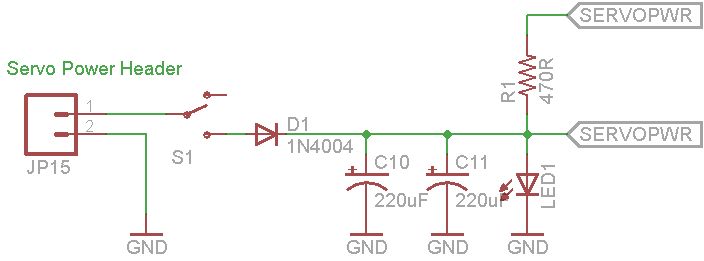
The servo power supply is a simple circuit I created to provide a simple and safe way to power your servos. The supply consists of a couple of capacitors to help supply extra current during high current demands on the battery, a diode to prevent reverse polarization, a convenient switch for power, and a small LED for a simple power indicator.
You will need the following in this step:
1x Switch
2x 220uF 35V Electrolytic Capacitors
1x Terminal Header Connector
1x 1N4004 General Rectifier
1x Small LED
1x 470 ohm Resistor
Various Jumpers / Wires
First connect the switch, diode and terminal for the battery.
Next add the filter capacitors.
Finally add the power indicator led and current limiting resistor.
Next we will build the servo interface circuit.
Step 3: Servo / Microprocessor Interface
The servo / microprocessor interface is a simple interface designed to make it easy to hook up servos to the Arduino and apply the proper power and grounding circuitry for the servos. In this example I show a bank of 4 servos. It is easy enough to add more servos by duplicating this bank. For example, duplicate it once for 8 servos or twice for 12 servos total.
The interface to the Arduino is quite simple and consists of just a current limiting resistor. The resistor really isn’t necessary but I like to play it safe and protect my Arduino whenever I can. Adding the resistor will prevent your Arduino from sourcing too much current to the control wire of the servo.
You will need the following in this step:
4x 100 ohm Resistors
4x Three Pin Terminal Headers
Various Jumpers / Wires
First add the resistors to the breadboard.
Next add the three pin terminal headers
Finally connect everything to proper buses (Right most pin is ground, middle is servo power)
Depending on how permanent you want it you might want to apply a liberal coat of hot glue to all the headers on the board. That will save you from having to pull the terminal headers from the connectors which they will inevitably stick to when you pull them off.
Next we upload the firmware.
1x BreadBoard
1x Battery 6.0-8.0Vdc
1x 1N4004 Diode
2x 220uF 35V Electrolytic Capacitors
4x 3 Pin Headers
For more detail: Série Servo-Contrôleur Arduino