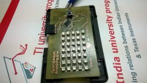
Badges are amazing things. Better when you make your own. I was about to attend the 1st MakerFest at NID, Ahmedabad and thought of taking something unique to the event. Badge was a great option and suited the maker theme of the event. So, sitting down with a pen and paper i drew what it would look like and came up something that could be retro-fitted to a usual boring office badge and would have a LED array to display text messages , the obvious a rechargeable battery ,light weight and of course infinitely hackable, just in-case people wish to remake it, which seldom is the case.
For the LED array we could use the usual LED Matrix,5×7 seemed to be a good size comfortable for both the pins and programmer. But..
The LED Matrix available in stores nearby had a lot of issues:
- Profile was too thick
- The sizes available were either too big or too small for a 5×7 size.
- Came with no datasheet, which meant bull work required to find out all the R and C values. Dahh!
So, I had to make a tough choice of soldering 35 LEDs which meant the PCB was going to be Dou.Double Sided (Literal stammering). I had never done double sided at home. But it was never too late and that difficult. Basically you have to align two sides and just slip in the copper clad , tape it , iron it and etch it and then Hope is all you need !
FYI, that ‘basically’ came after i spoilt one full PCB.
PRO-TIP: You can have some alignment marks out of the scope of PCB in different directions in the dimension layer. Now when you align the front and back you just align the marks. Check this instructable i used as a reference. Open Badge: The LED Badge
The major elements on the PCB were:
- LED Matrix
- A MSP430G2553 microcontroller brain
- A ULN2803 Darlington Driver to sink the current
- A USB connector to charge the battery
- A SBW connector to program the MSP430
- A Switch to change the message
- A Li-Ion battery from a Discarded Phone
- Current limiting and Pull up resistors
- Decoupling Capacitors
- A REG1117 Regulator for MSP430
Schematics and PCBs took 3 days of part-time work. Etching, Drilling and Soldering took a nighter. I had a provision to use the PCB directly as the badge with two big drill holes on the top.
Check out the images below:
Read more: Open Badge: The LED Badge

