This time I’ll show how I used an Arduino to control a relay module with eight channels.
Arduino in offers several advantages such as:
– Open source;
– Easy programming;
– You can assemble your own board;
– Is supported on various forums on the Internet;
– Has several “shields” (facilitates the use of it with sensors, for example.)
– Among others.
The idea I had was to create a simple programmable hardware. Where only would create a different software for each application.
Just as our computer. What we do (generally) is add a software The hardware remains the same.
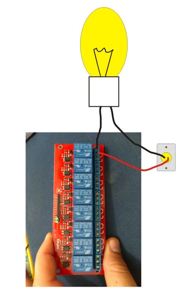
We can control larger loads within the limits of current and voltage relays. For example, connecting a ventilator, an appliance, among others.
Step 1: Materials
Below the list of materials:
– Arduino board;
– Sensor shield;
– 8-channel relay module;
– Wires;
– 11.1V battery
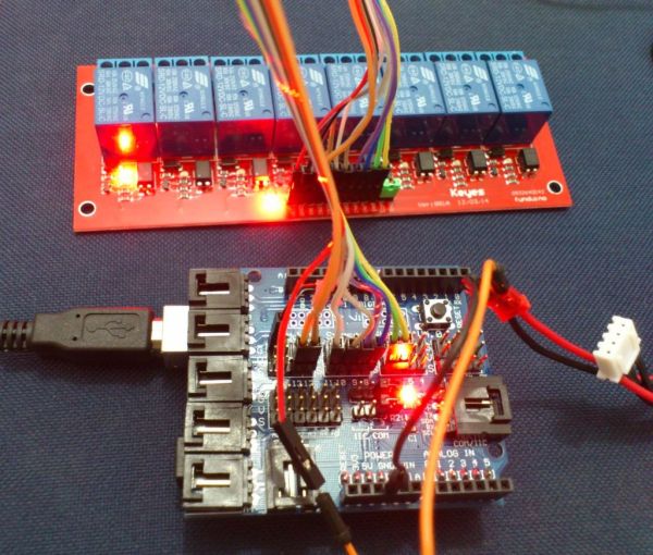
Step 2: Mounting
Mount the sensor shield on Arduino Boar and connect the shield to the relay modulde following the statement below.
link:
module -> Shield
in1 -> pin 13
in2 -> pin 12
in3 -> pin 11
in4 -> pin 10
in5 -> pin 9
in6 -> pin 8
in7 -> pin 7
in8 -> pin 6
Take care not to invert the wires.
The battery is connected as follows: A wire was added to the negative pole connected to GND and the shield and the other of the DC relay module.
The module was connected to the wire GND which is the same shield plate Arduino.
Step 3: Connecting and Programming
After assembling the hardware, just plug in and program the Arduino.
The following program was done to test the relay module. Works like the lights of the “Knight Rider”. The effect is quite interesting. Hope you enjoy.
Logiciel:
Logiciel:
int pinArray[] = {13, 12, 11, 10, 9, 8, 7, 6};
int count = 0;
int timer = 50;
void setup(){
for (count=0;count<7;count++) {
pinMode(pinArray[count], OUTPUT);
}
}
void loop() {
for (count=0;count<7;count++) {
digitalWrite(pinArray[count], HIGH);
delay(timer);
digitalWrite(pinArray[count + 1], HIGH);
delay(timer);
digitalWrite(pinArray[count], LOW);
delay(timer*2);
}
for (count=7;count>0;count–) {
digitalWrite(pinArray[count], HIGH);
delay(timer);
digitalWrite(pinArray[count – 1], HIGH);
delay(timer);
digitalWrite(pinArray[count], LOW);
delay(timer*2);
}
}
– Sensor shield;
– 8-channel relay module;
– Wires;
– 11.1V battery
For more detail: Larson Scanner avec le Module de Relais à l'aide d'Arduino