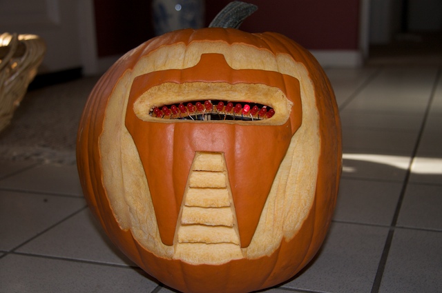
This has été done before. There are several good ways to do it: most use either a 555 timer chip and decimal counter chip, or an Arduino. Stefan and I used an Arduino (Boarduino, technically) which limited our scanner to 14 LEDs. No problem — 14 gives a nice scanning effect!
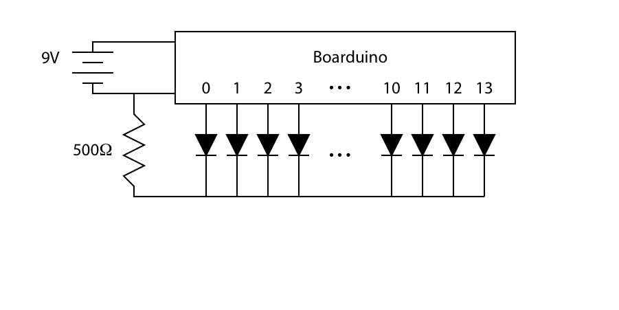
Here’s how we wired it: the numbers on the Boarduino block refer to the digital lines d0–d13.
// Cylon pumpkin driver
// Eric Ayars
// 10/24/09

#define MAXLIGHT 14

byte Wait = 50;        // Time each light is on, in ms
byte EndWait = 250;    // Time all lights are off at the ends

void setup() {
// Set all pins to output
for (byte j=0;j
pinMode(j,OUTPUT);
}
}

void loop() {

// Count up from 0 to 13, setting the light
// for each count.
for (byte j=0;j
digitalWrite(j,HIGH);
delay(Wait);
digitalWrite(j,LOW);
}

// Pause at the end
delay(EndWait);

// Count back down from 13 to 0, setting lights
// as it goes again.
for (int j=MAXLIGHT-1;j>=0;j--) {
digitalWrite(j,HIGH);
delay(Wait);
digitalWrite(j,LOW);
}

// Pause at the end
delay(EndWait);

}
Here’s Stefan with the completed “eye-bar”. We didn’t have a section of proto-board long enough to hold the entire scanner, so we split a long piece and spliced it together in the middle with short wires. This gave us the option of bending the unit in the center, which proved handy when mounting it in the pumpkin!
Rather than solder the eye-bar directly to the Boarduino pins, we soldered the wires to 8-pin female headers that then connected to the Boarduino. We labeled the headers to avoid confusion. 🙂 One side of the Boarduino has pins 0-7, and the other side has pins 8-13 and a connection to ground.
For more detail: Cylone De La Citrouille À L'Aide D'Arduino