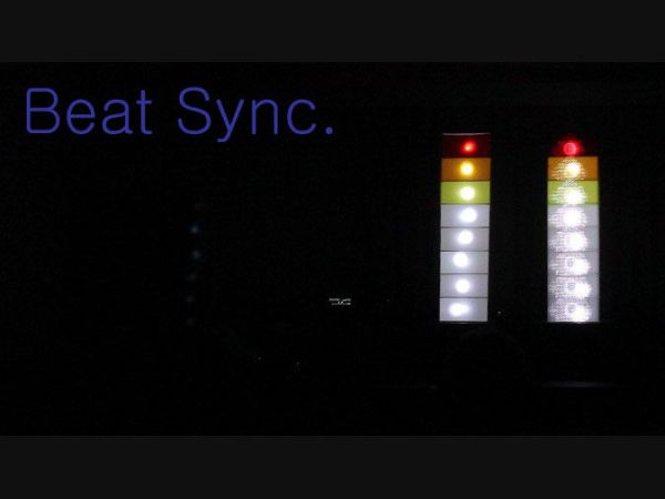
Beat Sync is a single frequency audio spectrum volume meter. It can isolate around a certain frequency ( I choose the bass ) and display it on a creative 8 segment LED bar graph. This is meant to be quite simple, yet allowing room for more difficult upgrades. It is built around the Arduino Open Source Environment. The circuitry is also quite simple.
So if you want to show off at your next house party or just make something cool to add some visualization to music, lets go!
 9
9
Step 1: Parts List
Basic
– Arduino UNO (or similar)
– 8 Super Bright LEDs
– 8 Resistors
– Wire/Ribbon Cable
– 3.5 mm Female Connector
– Soldiering Equipment
– Poster Board
– X-acto Knife
– Audio Equipment
– Mini Breadboard
– Mini Blank Circuit Board
– Heat Shrink
Additional
– 10 k Potentiometer
– Potentiometer Knob
– Colored PVC/Arcylic Film
– Diffuser
Step 2: The Enclosure
The enclose is pretty much a shelf. It can be made out of wood, plastic, or poster/cardboard. Then you can choose to glue the pieces together, make them interlocking or nail/staple gun them. In the spirit of recycling et reusing, I have found an interlocking cardboard design works well.
The dimensions are kind of up to your likes, whether you like squares or rectangles. This design gives more rectangular segments but you can draw it out before hand to see what it could look like.
1 – 8″ * 24″ (back)
2 – 4″ * 24″ (sides)
8 – 4″ * 8″ (dividers)
I left the one side uncut and had to ducktape the other(because I accidentally cut it). It folds into nice 90 degree edges that way.
NOTE – The dividers have edges that extend past the 8″ width to meet flush with the sides. The sides also have notches cut into them. You should be able to figure out a spacing that makes sense.
A laser cutter would work much better than blades or saws.
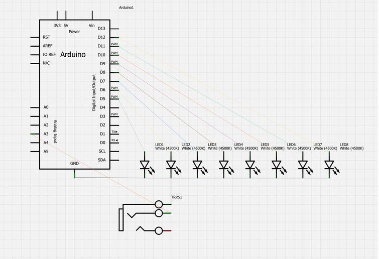
Step 3: The Circuity
The circuit is fairly simple although spread out when all said and done. The 8 LED’s anode legs are connected to the Arduino’s digital output pins(5-12) and the grounds are joined together. — Based on all rational electrical knowledge you should put in current limiting resistors between each anode and the Arduino, but because the LEDs are powered for such a short time, I believe it is simpler without them. —
The 3.5mm female audio connector’s ground should be joined with the LED’s common ground and then to the Arduino. — The ground on the audio connector should be the furthest from the outside. —
The Right or Left channel of the audio connector will be attached to one of the Arduino’s analog input pins.
Now for the code…
The breadboard and schematic view were done in Fritzing!
Step 4: The Code
The code relies on a Fast Fourier Transform Library, which can be found here. The FFT, in short breaks down the audio signal into 14 frequency bands and from that this project continues with the lowest. The bass… Then some if-else statements to light up specific LEDs.
Here is the code as in Arduino 1.0.1
//
// Beat Sync
// A music visualiztion device.
// Created by
// Carl Smith
// [email protected]
//
#include <fix_fft.h>
int led[] = {5,6,7,8,9,10,11,12};
int x = 0;
char im[128], data[128];
char data_avgs[14];
int i=0,val;
#define AUDIOPIN 3
void setup()
{
for (int i = 0; i <8; i++)
{
pinMode(led[i], OUTPUT);
}
Numéro de série.begin(9600);
}
void loop()
{
for (i=0; i < 128; i++){
val = analogRead(AUDIOPIN);
data[i] = val;
im[i] = 0;
};
fix_fft(data,im,7,0);
for (i=0; i< 64;i++){
data[i] = sqrt(data[i] * data[i] + im[i] * im[i]); // this gets the absolute value of the values in the
//array, so we’re only dealing with positive numbers
};
– 8 Super Bright LEDs
– 8 Resistors
For more detail: Beat Sync à l'aide d'un Arduino