Hello my name is Chipsy,
I’m French, reading instructables since at least 2 years, it is the first entry i make on this website.
Why i made this project :
I have a small homecinema system in my living room, with a projector and a commercial motorized projector screen.
I have a big mirror on the left wall, it makes the room brigther, but when watching a movie you want a dark room, and we could see reflections of the movie in it (very annoying) so i installed a grey/black blind i found in a DIY shop, it was a great fix.
Now i had to get it down then up every time by hand, so i tough “why not motorize it?”
Why i didn’t just remove the mirror ?
The mirror is embedded in the wall, and it is nice when not watching a movie, it expands the living room. So i wanted to keep it, but still be able to watch a movie without seeing the reflections in the mirror.
Step 1: “Reverse” engineering the projector screen motor controller
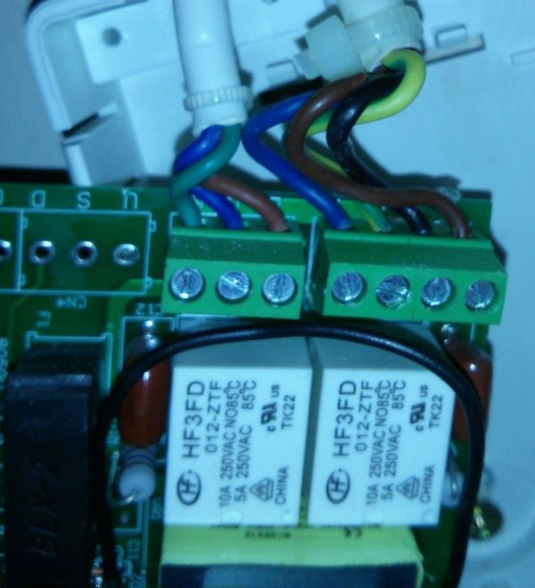
The existing controller for the projector screen is an integrated circuit that drives the screen motor.
It is controlled via an RF remote.
I grabbed my multimeter, and was able to find 12V on the relay coils.
So i soldered one wire to each relay coil (the terminal that gets down to 0V when the relay is “OFF”), plus one wire for GND.
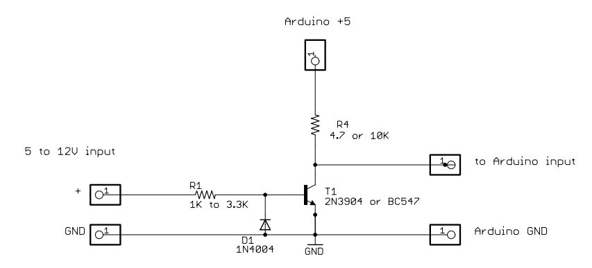
Step 2: High level shifting ( 12V detection circuit with arduino )
The idea with this circuit is being able to “sense” with the Arduino weither the projector screen is going UP or going DOWN.
This circuit works like this :
– When current is provided on the base of the transistor, the current flows from Arduino 5V to GND, the Arduino INPUT is then HIGH.
– When NO current is provided on the base of the transistor, the Arduino INPUT is connected to GND, and then the INPUT is LOW.
I used two transistors (TIP122), one for each relay of the projector screen.
Now i am able to know when the projector screen is going down, or is going up.
Step 3: Motor controller ( H-bridge using relays )
To control the motor, i will be using an H-bridge with a DPDT relay like you can see on this schematic below.
If you want more details, look on this page :
http://oomlout.com/a/products/ardx/circ-11/
This circuit allows the motor to run in forward and reverse weither we set the Arduino pin HIGH or LOW.
The problem with this circuit is that it doesn’t allow us to stop the motor *gasp*
In order to stop the motor when we want it, we will need to unplug one of the motor wires, and plug it into another bit of circuit with a kind of Switch hooked up to another Arduino pin.
I did that by inserting another relay in my circuit ( an SPST or SPDT relay will do fine ), controlled by another transistor ( hooked up to another Arduino pin set on OUTPUT )
I tested the circuit with two LEDs :
Arduino
Transistor
For more detail: Automatique aveugle relié à l'existant, l'écran du projecteur à l'aide d'Arduino