In this Instructable I am going to show how to make a program in Processing that analyzes sound on your computer and sends data to an Arduino that controls an LED matrix to show the spectrum analysis.
I will be explaining where to get materials, explaining the coding and wiring needed and providing example programs that can be adapted.
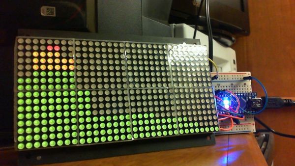
I will be using an Arduino Nano and and a 32×16 LED Matrix from Sure Electronics.
Step 1: Required Materials/Software and Where to Get Them
The required materials are:
1) An Arduino(doesn’t really matter which version/variant)
2) LED Matrix (for this Instructable, I use a 32×16 bicolor matrix, but any matrix should work)
3) A driver chip if your LED matrix doesn’t have them integrated, I will be explaining this in more depth.
Inexpensive LED Matrices: Sure Electronics: http://stores.ebay.com/Sure-Electronics
The display I use: https://www.ebay.com/itm/254190275503 hash=item3b2eebcbaf:g:Ix4AAOSwJZRcp95J
Required Software:
1) Arduino IDE (I am using version 1.0) found here: http://arduino.cc/en/Main/Software
2) Processing IDE found here: http://processing.org/download/
Step 2: Wiring
The wiring for this matrix from Sure Electronics, wiring is really simple. The 32×16 bicolor(red, green) uses four HT1632C driver chips integrated into the back of the matrix. The driver chips are what are actually responsible for controlling all the LEDs in the matrix. This particular board is 32×16 ‘pixels’ so to speak. But this is a bicolor matrix so there is actually 1024 LEDs on this board. Now that’s a lot of LEDs, but because of the driver chips, we only use 4pins plus +5V and GND to connect the Arduino to the display. This display can also be daisy chained to 3 other displays and still only need 4 pins from the Arduino.
For other matrices, the wiring can range in difficulty. A standard 8×8 matrix needs 16 pins to control it without a driver chip. I will explain about driver chips in the next step.
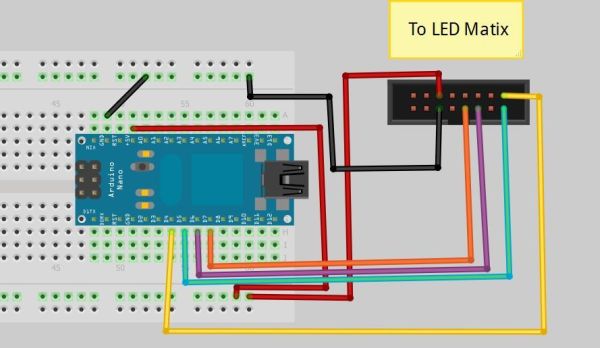
The 4 pins needed are for the display’s Data, CLK, CS, and WR. The connector on the driver chip should be labeled with these or be stated on the chip’s datasheet. I have included the wiring for the 32×16 display as shown below. The pins used on the Arduino below can be changed, but the values in the coding must be changed to match.
Step 3: Driver Chips
For a 8×8 matrix, I would suggest getting a MAX7219. This driver chip can control a 8×8 matrix, or 8, 7-Segment displays and only use 4 pins plus a +5V and GND. The MAX7219 can also be daisy chained to another 9 drivers. There are other driver chips available, but the MAX7219 has an Arduino library in existence which makes coding easier for beginners.
For more detail: Arduino Traitement De L'Analyseur De Spectre Audio