We all know about Arduino. It is one of the most popular open source micro controller board which is highly useful for doing DIY projects. This Arduino based 3-Way Traffic Light Controller is a simple Arduino DIY project which is useful to understand the working of traffic lights which we see around us. We have covered a more simpler version of traffic lights in this traffic light circuit. Here have demonstrated it for 3 sides or ways. Now let’s get into the project…
Components Required:
- 3*Red LED Lights
- 3*Green LED Lights
- 3*Yellow LED Lights
- 3*220ohm Resistors
- Breadboard
- Male To Male Connectors
- Arduino Uno With Ide Cable
Circuit Explanation:
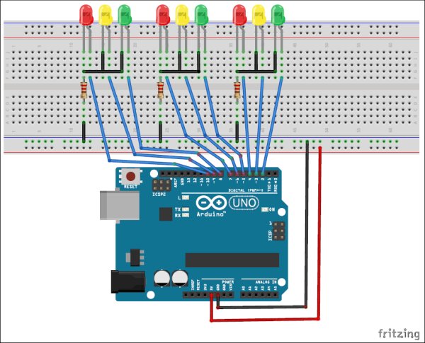
The circuit Diagram for Arduino Traffic Light Controller project is given below:
It’s pretty simple and can be easily built on bread board as explained in below steps:
- Connect the LEDs in the order as Red, Green, and Yellow in the breadboard.
- Place the negative terminal of the LEDs in common and connect the 220ohm resistor in series.
- Connect the connector wires accordingly.
- Connect the other end of the wire to the Arduino Uno in the consecutive pins(2,3,4…10)
- Power up the breadboard using the Arduino 5v and GND pin.
Program and Working Explanation:
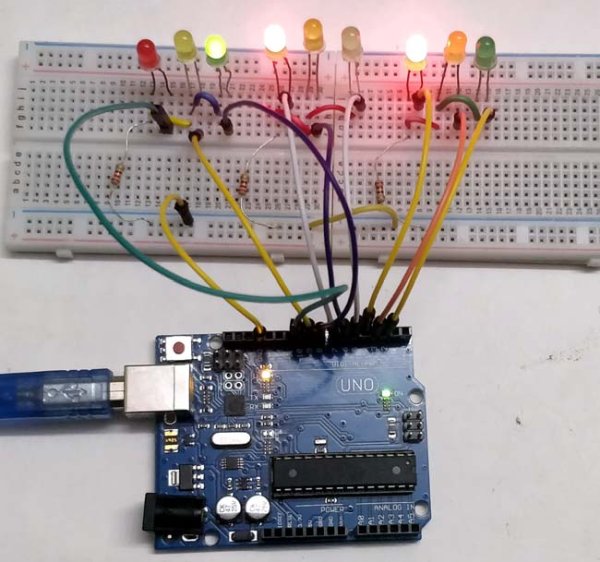
The Arduino Traffic Light Controller Project code is not complex and is easily comprehensible. We have shown a demonstration of traffic lights for a three-way road, with LEDs lighting up on all three sides in a specific order, just like real traffic lights. At one point, there may be two Red lights on one of the sides and a Green light on the other side. Yellow light will glow for 1 second during the transition from the red light to the green light, with the red light glowing for 5 seconds, followed by the yellow light for 1 second before the green light comes on.
In the program, first we have declared pins (2,3…10) as output in void setup() for 9 LEDs (three on each side i.e. forward, right and left side).
   void setup() {
  // configure the output pins
  pinMode(2,OUTPUT);
  pinMode(3,OUTPUT);
  pinMode(4,OUTPUT);
  pinMode(5,OUTPUT);
  pinMode(6,OUTPUT);
  pinMode(7,OUTPUT);
  pinMode(8,OUTPUT);
  pinMode(9,OUTPUT);
  pinMode(10,OUTPUT);
}
Then in void loop() function we have written the code for traffic lights to be turned on and off in sequence as mentioned above.
void loop()
{

  digitalWrite(2,1); //enables the 1st set of signals
  digitalWrite(7,1);
  digitalWrite(10,1);
  digitalWrite(4,0);
  digitalWrite(3,0);
  digitalWrite(6,0);
  digitalWrite(8,0);
  digitalWrite(9,0);
  digitalWrite(5,0);
  delay(5000);
  ..... ....
  ..... ....
The Arduino Traffic Light Controller Project code is not complex and is easily comprehensible. We have shown a demonstration of traffic lights for a three-way road, with LEDs lighting up on all three sides in a specific order, just like real traffic lights. At one point, there may be two Red lights on one of the sides and a Green light on the other side. Yellow light will glow for 1 second during the transition from the red light to the green light, with the red light glowing for 5 seconds, followed by the yellow light for 1 second before the green light comes on.
L' complete Arduino code and Video for this Arduino Traffic Light Project is given below.
Code
Video
Source: Arduino Basée À 3 Voies De Circulation Contrôleur De Lumière