Step 1: Get all the parts
– 4 standard wall outlets
– A four bay plastic outlet box for old construction
– An 8 channel relay board
– A three prong appliance cord
– A four bay outlet face plate, or the laser cut version attached (Red cut, Blue etch)
– 8 half inch #6 machine screws, 4 matching nuts
– 4 one and a half inch #4 machine screws with nuts and one inch nylon stand-offs
– Some wire, 10 female and male header pins, solder, etc.
Tools needed:
– A soldering iron
– A multimeter
– A drill
– A screwdriver
– Wire cutters
I got all the materials from Home Depot and Amazon. In total, it cost about $50.00 for all the parts.
This is a really simple project, but it does require experiences with drills and soldering. There are great tutorials on instructables for these tools if you do not already have these skills.
PLEASE NOTE: Working with AC power is dangerous. Don’t hurt yourself, and don’t blame me if you do.
Step 2: Snip the outlets
I wanted individual control of each outlet, versus both outlets being powered on at once. To do this, you have to cut the tab between the GOLD screws on all the outlet pairs. The GOLD screws are on the hot side, the SILVER screws are on the neutral side. It should say this on the bottom of the outlet pair. Use your wire cutters to snip this tab. You can use a multimeter to make sure the connection is broken. The cold side tab can remain intact as we will be wiring them all together anyway.
Step 3: Wire the grounds and colds
Cut yourself six 3inch lengths of wire. I used 18 gauge wire, but 14 gauge would probably be better. Use at least 14gauge wire – I went back and rewired mine based on feedback in the comments. Strip and bend each end into a C shape. Use three of these wires to connect all the GREEN ground screw terminals, and the other three to Connect the SILVER neutral terminals. Since we left the cold side tabs in tact, we only have to use one screw per outlet pair. Use your multimeter to ensure that all the GREEN screws are connected and all the SILVER screws are connected (even the ones without wires).
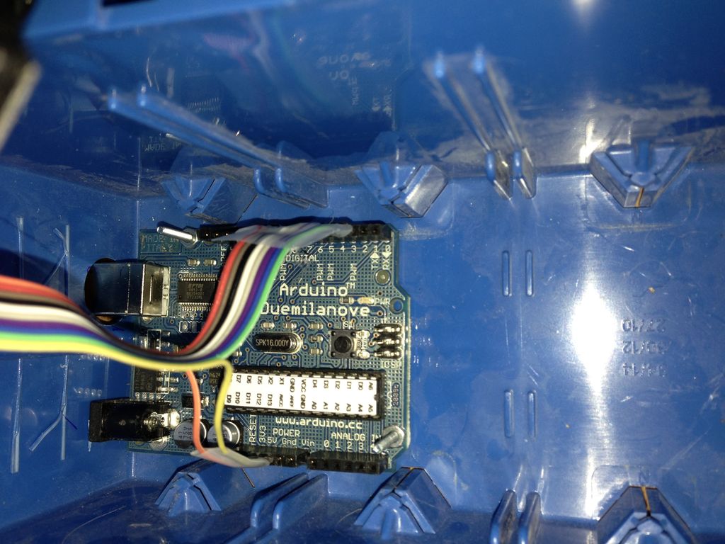
Step 4: Add the relay
Now, cut 8 lengths of wire (about 4-6 inches depending on the outlet’s position), strip the ends, and C shape one of them. One C end goes to each of the 8 GOLD screws, so that each GOLD screw has its own wire. The other strait end of the wire goes into the really array. PLEASE NOTE: In the photo I have it wired up wrong! The wires should go into the MIDDLE terminal of each relay’s 3 terminals, NOT the LEFT terminal.
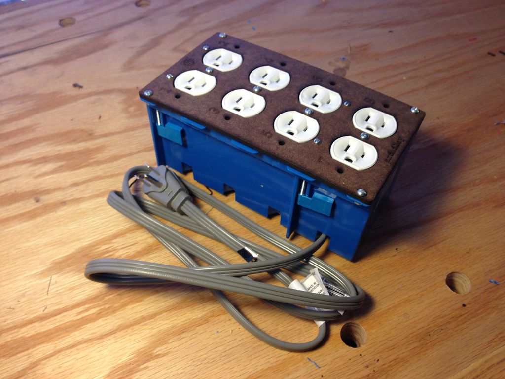
Step 5: Mount some stuff
You can now mount the outlets to the faceplate with the #6 screws, and the relay array to the faceplate with the #4 screws. Check to make sure you’ve got outlet one going to relay one and outlet two going to relay two, etc.