So this Lazy Old Geek purchased a Laser Cross. I created a manual leveling Laser Cross to use for aligning stuff on my drill press:
http://www.instructables.com/id/ManualLevelingLaserCross/
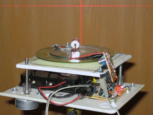
Well, being a Geek I decided to make an automated platform that adjusts automatically with an Arduino.
Well, the picture may look a little scary but I’ll break it down into little bitty parts.
Step 1: Parts Lists
Parts List Laser Assembly
650nm <5mW Laser Cross Module Diode $4.85 ebay
The laser diode in the module is an HLM1230
I made my laser current source using this:
http://www.rog8811.com/laserdriver.htm
Parts List Laser Current Source
LM317 regulator $0.24 TaydaElectronics.com
100 Ohm potentiometer $0.21 TaydaElectronics.com
1N4001 diode $0.01 TaydaElectronics.com
10uFd 50V capacitor $0.03 TaydaElectronics.com
47 Ohm resistor $0.01 TaydaElectronics.com
(used instead of the two 10 Ohm resistors)
PCB I used a hunk of the following:
5* Breadboard Bread Board Prototype 432 Points 5*7cm
$1.39 ebay
Did not use a pushbutton
Parts List Tripod Mount
6 x AA battery holder with 2.1mm plug AdaFruit.com $5.00
http://www.adafruit.com/products/248
1 used plastic cutting board
1 discarded music CD player mechanical assembly
1/4 x 20 nut
Miscellaneous 6-32 and 10-32 hardware
2 Mitsumi M35SP9 stepper motors salvaged from old printers. These are unipolar stepper motors. If you have or get different stepper motors, you may have to design your own interfacing and modify the software accordingly.
1” 7/16” vinyl tubing
Hot shoe bubble level $0.99 ebay.com Hot shoe is a camera term.
Parts List Arduino-clone
L.O.G. $10 Arduino (modified)
http://www.instructables.com/id/LOG-10-Arduino/
1 ULN2003 Darlington driver $0.20@ TaydaElectronics.com
2 BS170 FETS $0.26@ TaydaElectronics.com
1 Dip switch 4 position piano $0.34@ TaydaElectronics.com
1 FreeScale MMA7361 Module inclinometer accelerometer. I got my in an ebay auction for $9 but they’re available for $10-$14 from ebay.
PCB I used another hunk of the following:
5* Breadboard Bread Board Prototype 432 Points 5*7cm
$1.39 ebay.com
Totally cost is less than $30, most for Arduino-clone and battery box.
I am not going to go into the details of making the Laser drive current source as it is explained in the above website.
The HLM1230 is designed for 25mA or less. This is how I determined the 47 Ohm resistor value. (See picture) I added a 2.1mm power plug from my scrap pile.
Step 2: Laser Safety and Information
***********************WARNING**********************************
Any laser you buy will have a DANGER stick similar to this one. The particular laser that I am using is 5mW. The typical laser pointer is 1mW. Now I’m haven’t researched laser safety that much but as I understand it, even a 1mW can damage the eye if looked at directly. This one is five times more wattage so use carefully. Do not aim it at a person or animal.
***********************WARNING**********************************
Some readers may wonder how the cross is generated. Search Ebay.com for this: 650nm <5mW Laser Cross Module Diode
Some of the pictures (See picture) show that this module actually projects a red cross. This is created by a special lens used in this module. You can adjust the orientation by rotating the lens mount.
By the way you can get lenses that generate just lines or multiple lines and other patterns.
Step 3: Tripod mount
My original design used two music CD cases. They seemed to be fairly sturdy but not too heavy and about the right size. However, the plastic is rather fragile to work with. I ended up with a lot of cracks and it wasn’t very stable. So my next design uses a stiff plastic cutting board, I got from my cousin.
Design: I decided on a three point design with a bottom and top piece of plastic. The bottom piece is attached to the tripod. The top is attached to the bottom with three long bolts. The upper left corner is a fixed pivot point, the upper right and lower left corners have bolts attached to stepper motors so that the top piece can be leveled. After the problems I had with the CD cases, I decided to design this one a little better and started with a drawing for the base. (See picture)
Tripod base:
My CAD program isn’t that good and I’m not very good at using it, so the drawing is not really clear. From the plastic cutting board, I cut a 5 ¾” x 7” piece.
In the center I marked an X for the hole where the tripod nut will go.
Then I drew four lines to locate where the three points for the pivot point and stepper motors go.
Tripod Mount:
In the center, drill a 3/8” hole. This was determined by measuring across a ¼ x 20 nut. All tripods use ¼ x 20 bolt to mount the camera or in this case my fixture. The hole is a little smaller than the nut.
To embed the nut: Thread a ¼ x 20 nut onto a bolt. (The nut gives you more leverage with a wrench to pull the nut into the plastic) Put a washer on the bolt. (See picture) Slip the bolt through the central hole in the bottom piece and put a nut on the bolt. (See picture)
Center the nut over the hole. Use a 3/8” wrench on the top side to pull the bottom nut into the plastic. (See picture)
Measure and draw the four lines on the base. Choose the corner for the pivot. I chose the upper left corner.
The upper right and lower left corners are the stepper motor corners. (Lower left is not used) They are 4.25” from the pivot corner. For these, you also want to mark the locations for the mounting hardware. I found the specifications for the M35SP9 stepper motors. The mounting holes are 42mm apart or 21mm from the center.

I used 10-32 hardware for the standoffs. So drill a 3/16” hole for the pivot. I used 6-32 hardware to mount the stepper motors so I drilled 9/64” holes for the motors.
I left the gears on my stepper motors so I drilled 5/8” holes using a spade bit for the gears and tubing to pass through.
Pivot point: The only long 10-32 bolt I had was 2 7/8” so I put a nut on it, screwed it through the pivot hole and put a nut on top. I put two nuts on the bolt screwed them down about 1/2” for the pivot point and tightened them together.
Near the motor locations, I also drilled a couple of big holes for the wires to pass through. The motors will be mounted underneath but the wiring will go to my custom Arduino on top of the base.
Steppers: I installed the steppers with 6-32 hardware. I cut two short pieces of 7/16” vinyl tubing and stuck it over the gears. Then I stuck two 10-32 x 2” stove bolts into the tubing. If everything goes right, the three bolts will line up with the top assembly.
[box color=”#985D00″ bg=”#FFF8CB” font=”verdana” fontsize=”14 ” radius=”20 ” border=”#985D12″ float=”right” head=”Major Components in Project” headbg=”#FFEB70″ headcolor=”#985D00″]Arduino
regulator
resistor[/box]
For more detail: Auto Leveling Laser Cross using Arduino