ArduSensors are open source plug-in-play sensors for Arduino. These were originally made for beginners to get started with Arduino, a very cool electronics prototyping platform, but anyone can use them. I still play around with them all of the time, and I bet a ton of people that are experienced with electronics still love them. That’s why ArduSensors fit the whole crowd. ArduSensors fit directly into the power pins and A0, like a mini shield. They come with male headers, not stackable headers, so that you can plug them easily into the Arduino. The entire line of ArduSensors are available now at my website, www.qtechknow.com if you would like to make a purchase, or check them out.
Types of ArduSensors
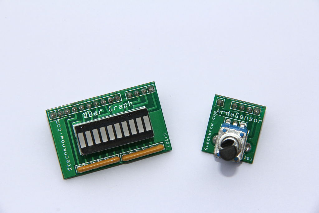
I will cover the ArduSensor Pot and the QBar Graph in this Instructable. I have 12 ArduSensors available now and more coming soon. The ArduSensors currently available include: ArduSensor Arcade, Button, Fart, Flex, Force, Knock, Light, Magnet, Phototransistor, Pot, Switch, and Temperature. I carry a shield for Arduino that can read up to 4 different ArduSensors at once and have 3 different output options. Also, if you would like output, there is the QBar Graph, QColor, and QBuzz. The QBar Graph is an LED Bar Graph that goes into the digital pins on the Arduino, the QColor is an RGB LED that goes into the digital PWM pins on the Arduino, and the QBuzz is a buzzer add-on that can make many different noises!
Below are the Eagle files (the schematic and the PCB design), since ArduSensors are all open source.
 Pot.brd23 KBPot.sch52 KBQBar Graph TV2.brd39 KBQBar Graph TV2.sch82 KB
Step 1: Parts
All of the parts that are listed below you can get at Sparkfun.
Arduino UNO, Arduino Leonardo, or later
A computer running Arduino IDE 1.0.1 (free)
USB-B Cable (for programming the Arduino UNO only)
USB micro-B Cable (for programming the Arduino Leonardo only)
The ArduSensor Fun Pack includes the ArduSensor Pot and QBar Graph.
ArduSensor Pot Kit from my website, Qtechknow.com includes:
Qtechknow ArduSensor Pot PCB (not yet available)
Potentiometer
Male Headers (5)
QBar Graph Kit from my website, Qtechknow.com includes:
Qtechknow QBar Graph PCB (not yet available)
10 Segment LED Bar Graph
Resistor Network – 330 Ohm (2)
Male Headers (14)
Tools:
Diagonal Cutters
Soldering Iron
Solder
Step 2: ArduSensor Pot Assembly
The ArduSensor Pot is a potentiometer that you can use in any of your Arduino projects. Let’s teach you how to build your kit:
Step 1: Take out all of the parts.
Step 2: Put the potentiometer on the front of the PCB, in the 3 holes in the middle and the two big holes on the lower corners.
Step 3: Flip the PCB over and solder the potentiometer in place. Solder all 5 of the holes that your potentiometer is placed in, even the two big holes.
Step 4: Get your Arduino out (this step doesn’t depend on which Arduino you use). Cut the male headers so that you have a 1 pin male header separate from the other 4 pins. Put the long side of the 1 pin male header into A0 on the Arduino. Put the long side of the 4 pin male headers into VIN, GND, GND, and +5V, which should be all together. Now, put the ArduSensor PCB (with the potentiometer already soldered) onto the 1 and 4 pin male headers. Solder the holes for the headers in place. I have found this tip to be very helpful in keeping the PCB perpendicular to the male header pins.
You are now finished assembling your ArduSensor Pot, and ready to program (or if you like, copy my programs)!
Step 3: ArduSensor Pot Coding
Plug your Arduino UNO or Arduino Leonardo into your computer via the cable that corresponds to that Arduino. If you are a first time Arduino user, you can install the drivers necessary to use the Arduino here (on step 4 of this Arduino page). If you know how to use and run the blink sketch in the Arduino IDE already, select the COM port for your Arduino, and the correct board from the boards menu.
Download the example code for ArduSensors here. Press “Download as Zip” and unzip the folder. Double click on the ArduSensor-LED.ino sketch and run it on your Arduino by clicking on the right arrow key in the Arduino IDE. Plug your ArduSensor Pot into the Arduino (the 4 pin male header goes into VIN, GND, GND, and +5V, and the 1 pin male header goes into A0). ArduSensor-LED.ino is a program to make the built-in LED on D13 to blink at a rate specified by the value (in this case, how much you twist the knob) of the ArduSensor (in this case, the ArduSensor Pot).
For more detail: ArduSensor Fun Pack Plug-In-Play Sensors For Arduino