In the mid eighties synths manufaturers started a “less is better” process that led to barebones synths. This allowed the reduction of costs on the manufaturer side, but made the patching process tediuos if not impossible for the final user.
Manufacturers themselfs and third party companies realized optional boxes full of knobs and/or sliders to let you actually “play” with your synths tones, but these are silly overpriced nowadays and, as always, we are forced to find cheap solutions by ourself 😉
This project came from my need to easily program patches on some of my latest synths buy: a Roland Alpha Juno 2 and JX8P. It started as a simple SysEx controller, then it grow up on me and became something more complex, with other synths supported on the way (Korg DW8000, Oberheim Matrix 6/6R, SCI MAX) and a built-in sequencer.
In this instructable I will show you how to realize your own controller: a cheap tool that emulates those highly priced parameter control boxes… and more (continue reading for details…).
Step 1: What Exactly This Thing Is (and What Is Not…)
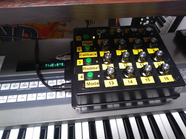
The MIDI SysEx and Control Change controller here is essentially a 16 knobs (potentiometers) and 4 buttons MIDI controller. The default sketch handles three “pages”, for a total of 48 synth tone parameters.
I made the controller compatible with control change MIDI messages (a simple and “global” type of MIDI message widespreadly used by synth manufacturers especially from the 90’s) and SysEx messages (another type of MIDI message, way less general and highly synth-specific heavily used in the 80’s).
In particular, the controller by default is compatible with:
– Roland Alpha Juno (1/2)
– Roland JX8P
– Korg DW8000
– Oberheim Matrix 6/6R (> 2.14 firmware)
– Sequential circuits MAX/SixTrak.
You can eventually enable the controller to act on any synth that can receive MIDI control change (CC) messages, but it’s disabled by default.
Being the open source nature of the project, it’s very easy to support any other synth of your choice (see the code step for details).
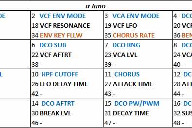
The tone parameters layout with all those number could be confusing at first, but it’s not “random” as it could look like: it follows the order of the manufacturer MIDI implementation chart. This was a design choice to keep the code simple and “universal”.
You can download picture sheets with the 4×4 “layout” I realized for Alpha-Junos, JX8P, DW8000, Matrix 6 and MAX/SixTrak on this page: blue parameters are those you can tweak while on page 1, black those on page 2 and orange those on page 3.
Even if the controller has no screen, toying with synths that show you what parameter is being tuned in real time makes the process of creating a patch a joy. The JX8P and Matrix 6, in example, are capable of this; the Alpha Juno, instead, do not show you the parameter being changed and makes things a little bit harder (but creating awesome patches is definitely doable and easyer than by using the built-in knobless interface); DW8000 has only numeric displays, but you can see your tweakins in real time so it places in between on this.
What about those buttons there?
Well, the first one (upper left in my layout) is for page surfing: jump to the next parameter’s page at each press of the button. LEDs will indicate which page you are in.
The second when pressed send the patch you where working on back to the synth (figure it: you made the patch of your life, then touched a program button on the synth surface and the button-specific patch was loaded… all your work have gone!). With this button you can send all the values the programmer had memorized during the last patching process. This patch recall process does not work if you press the randomizer again (randomization process overwrite all the parameters in memory) and it’s only effective on parameters you edited at least once. The latest patch is not kept in memory after shutdown.
The third is for a secondary function: the randomizer/patcher! Turn full anticlockwise the knobs you want the parameter they act on to lock to minimum value (i.e. oscillator LFO, oscillator envelope, etc.) or turn fully clockwise to maximise the value (i.e. oscillator mix volume, VCA volume, etc.) and press the button to start he randomization process for all other parameters.
The fourth button is there to activate an easter egg (sort of…) I placed in the code after noticing that the layout was perfect for… a 16 steps MIDI sequencer! Exactly: press the fourth button (MODE button), the controller will enter the “sequencer mode” and you will be allowed to trigger notes in a similar way those old analog sequencer did. Nice uh!
Press the MODE button again to go back to controller/patcher mode.
What about those LEDs?
There are 4 LEDs in corrispondence to each button (on the right of each button in my layout) ; these LEDs have multiple pourpouses:
1) they tell you wich parameters page you are in (upper LED is lit when you are in page 1, LED underneath is lit when page 2 is active, LED 3 is lit… you figured it yourself). We are limited to 3 pages ATM, but the code can be easily tuned to handle more pages;
2) the second LED indicate parameters page 2 AND is lit when the microcontroller is sending the previous patch (patch recall);
3) the third LED indicate parameters page 3 AND is lit during the randomization process.
The fourth LED do nothing in MIDI controller mode and is used for global MODE change.
All these functions are transmitted as MIDI messages, so in order to be effective, your synth must be capable/enabled of receiving and interpret this sort of messages!
Step 2: The “Hidden” 16 Steps Sequencer!
As said, while testing the controller I realized that it would be great to let a sequence of notes run so that I could tweak synth parameters and have a better idea of the final effect on the tone. I have a software sequencer (I like seq24 so much!), but this hardware is an almost PERFECT 16-steps sequencer! Then it was only a matter of code to implement it.
You can toggle between controller mode and sequencer mode by pressing button #4 (MODE button).
While in sequencer mode buttons work differently and LEDs give you new informations:
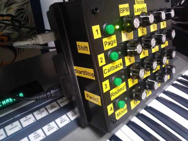
– the first button (SHIFT button) when pressed allows for tempo, note lenght, channels and octave modification; the tempo value is given by the position of the first potentiometer, the note lenght is computed from the second potentiometer position, MIDI channels from the third and fourth potentiometer positions and octave (-1 o up to +2) from the fifth pot. You can control tempo from 40 BPM (turn potentiometer #1 full counterclockwise while keeping button #1 pressed) to nearly 240 BPM (turn potentiometer #1 full clockwise while keeping button #1 pressed). You can set notes lenght to halfs note, quarter note, eights note, sixteents note by turning pot #2 while keeping the SHIFT button pressed. You can set MIDI channels (primary channel and secondary channel) from 1 to 16. The base notes range (from C2 to F#4) can be lowered of one octave or increased by one or two octaves.
By default tempo is set to 120 BPM and note lenght to quarter notes.
– the second button start and stop the notes sequence. As said, if you change mode by pressing the button #4 (MODE) while running the sequence you will enter controller mode but the sequence will continue to run.
– the third button is a PANIC! By depressing it all notes will be shut off.
– the fourth is used to toggle between global modes (pather or sequencer) when button #1 is not pressed, or between sequence modes (see in the folowing) when #1 is depressed.
In sequencer mode if you press the mode select button while keeping button #1 (SHIFT) pressed you can toggle between 3 different sequence modes:
1 – 16 steps mono sequence
2 – 16 steps poly sequence: notes one octave lower than those defined by pots are triggered too (this drains 2 voices per beat)
3 – 8 steps poly sequence, dual channel: two parallel 8 steps sequencies are sent to two different channels (CH1 and CH2 by default); by setting the same channel value both on the primary and seconday channels you can have two parallel 8-steps sequencies played by the same (polyphonic) synthesizer.
About LEDs: as soon as you enter sequencer mode, all four lights will light up. When you start the sequence, LEDs will follow the sequence (or the sequencies). I placed one LED every four potentiometers and is good enought for me. It would be simple to modify the sketch to handle 16 LEDs, one for each step thou.
The step sequencer miss features someone could find necessary: MIDI sync IN, steps hold (you can only shut a step off), CV out.
I have implemented clock OUT, but is someway buggy. I tried two approaches for this (one with and one without timer interrupts), but they both where imperfect (or a total fail). MIDI clock must be strict-perfect to work on the long term. A clock signal is sent anyway and you can disable it directly on the sketch (see later for details).
Notice that this step sequencer is MIDI, or digital if you prefer, so in order to work must be connected to a synth enabled to receive and interpret these kind of messages!
Step 3: Hardware Needed and Building
After all these words, let have some fun!
We are going the common Arduino way. I used an Arduino MEGA because of the high amount of analog inputs (we want a box full of knobby knobs, won’t we?! 🙂 ).
In particular, Arduino MEGA can handle 16 analog inputs (with some hardware tweaking, i.e. by muxing, you can increase this but we are not going this route here), so we are going to send the 48 MIDI messages via 16 potentiometrs. Each potentiometer will then control three parameters, one for each “page”; pages are selected by a switch button.
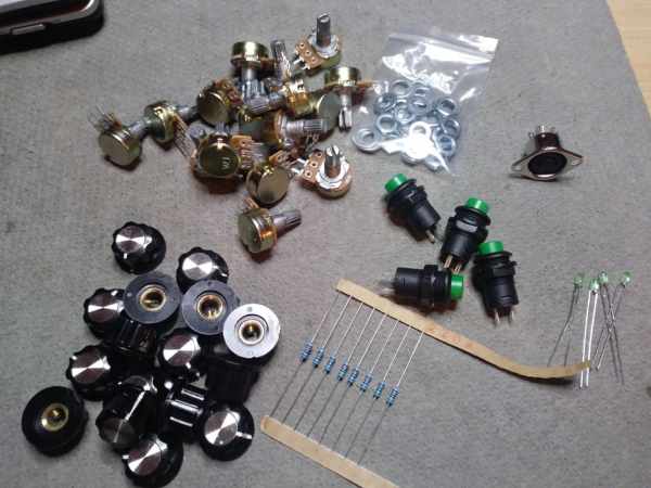
Hardware list:
– 1x Arduino MEGA
– 16x linear, single turn 10 K ohm potentiometers
– 16x pot knobs
– 4x momentary push buttons
– 4x LED
– 6x 220 ohm resistor
– 1x MIDI connector
– 1x ABS projects box
Some cable, solder wire and six – eight hours of spare time.
I used a perfboard and some pin headers to realize a sort of shield I soldered the resistors on and directed the cables. This has the advantage of letting you take out your Arduino and use it for other projects (we all run low on Arduino boards at some point!). It’s not mandatory anyway and another good approach could be to desolder the arduino MEGA pinheaders and solder cables directly in place.
I used 200 ohm resistors in place of 220 ohm resistors and they work perfect anyway; i would bet even 150 ohm resistors would work great (for both MIDI communication and LEDs).
To shape the box, I first applied some adesive paper on the box surface, measured whrere the holes should be drilled (I had 3 cm from hole to hole to let all the pots to fit) made the guide holes and then enlarged to the right size to let pots thread or buttons thread to pass with a mini drill. I spent more or less 2 hours to finish the box. I realized little holes too, and glued LEDs in place.
I also drilled a hole for the MIDI OUT connector and another for the arduino power connector (I used directly the built-in USB power connector and firmly locked the arduino MEGA in place).
WARNING: always ALWAYS wear eyes and hands protections while drilling, whatever material you are working on (plastic, wood, metals, composites… it doesn’t matter: you are at risk both with respect to power tools and chips of material eroded/fired from the moving tool).
Then, I placed all the pots and buttons and soldered the components as per attached picture. An effective way to reduce the weight of the final object (and lenght of cables) is to daisy chain all the pots both on the 5V line and GND line.
And before anyone asks: I know, that box I used is ugly! But it was free and nothing beats free 🙂
Source: (almost) Universal MIDI SysEx CC Programmer (and Sequencer…)