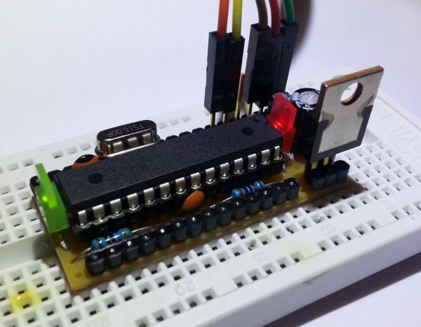
This Instructable will demonstrate the building of a bare bones (and really inexpensive… less than $5) Arduino compatible module that can be put together on a small piece of stripboard and can be used either on a breadboard or independently.
 The following links / similar projects were used as inspiration:
* http://www.instructables.com/id/Small-form-factor-DIY-Arduino-on-stripboard/
* http://tinkerprojects.blogspot.com/2012/06/minimal-arduino-on-small-stripboard.html
* http://shop.moderndevice.com/products/rbbb-kit
* http://txapuzas.blogspot.com/2010/07/paperduino-stripboard.html
The schematic is based off of the Arduino Pro Mini (http://arduino.cc/en/Main/ArduinoBoardProMini) and only differs in a few minor (optional) ways:
1. This design uses a more powerful voltage regulator
2. This design uses a more precise crystal (instead of ceramic resonator)
3. This design ditches the reset button (do you really need it?)
4. This design uses a 1k (instead of 10k) resistor for the power indicator LED
Prerequisites / Tools Required:
* Soldering Iron with fine tip
* Solder (fine) & Flux
* Utility Knife
* Mini needle-nose pliers (optional, but useful)
* Multimeter (or volt meter)
* An existing Arduino, or any other AVR programmer (needed to upload the bootloader)
* A USB-to-Serial TTL adapter (used to upload programs after the bootloader is in place)
Parts List (with an inexpensive source recommendation):
* $0.22 – 19 row x 8 column stripboard (less than 1/3 of a 94x53mm stripboard)
> http://www.taydaelectronics.com/small-stripboard-94x53mm-copper.html
* $1.00 – 3.50 – Atmega328P (or the ATMega168 or ATmega8 if they are enough for your needs)
> http://www.taydaelectronics.com/atmega328p-pu-atmega328-microcontroller-ic.html
TIP: You can get the older ATmega8 chips on eBay for around $1 (in a 10 pack) these days,
or the latest and greatest ATmega328P chips on eBay for around $2.20 (in a 5 pack)
* $0.11 – 28 pin DIP IC socket
> http://www.taydaelectronics.com/28-pin-dip-ic-socket-adaptor-solder-type.html
TIP: You can substitute 2x 14-pin lengths of SIP/DIP socket adapter for a higher quality socket
* $0.23 – LM7805 5V voltage regulator
> http://www.taydaelectronics.com/lm7805-l7805-7805-voltage-regulator-ic-5v-1-5a.html
* $0.10 – 16 MHz crystal
> http://www.taydaelectronics.com/16-000-mhz-16-mhz-crystal-hc-49-s-low-profile.html
* $0.02 – (2) 22pF ceramic disc capacitors
> http://www.taydaelectronics.com/10-x-22pf-50v-ceramic-disc-capacitor-pkg-of-10.html
* $0.03 – (3) 100nF / 0.1uF ceramic disk capacitors
> http://www.taydaelectronics.com/10-x-0-1uf-50v-ceramic-disc-capacitor-pkg-of-29.html
* $0.03 – 100uF 10V electrolytic capacitor
> http://www.taydaelectronics.com/100uf-10v-105c-radial-electrolytic-capacitor-5x11mm.html
* $0.03 – 100uF 25V electrolytic capacitor
> http://www.taydaelectronics.com/100uf-25v-105c-radial-electrolytic-capacitor-6x11mm.html
* $0.02 – Red LED 3mm
> http://www.taydaelectronics.com/led-3mm-red.html
* $0.02 – Green LED 3mm
> http://www.taydaelectronics.com/led-3mm-green.html
* $0.012 – 330 ohm 1/4 watt metal film resistor 1%
> http://www.taydaelectronics.com/330-ohm-1-4w-1-metal-film-resistor.html
* $0.012 – 1K ohm 1/4 watt metal film resistor 1%
> http://www.taydaelectronics.com/10-x-resistor-1k-ohm-1-4w-1-metal-film-pkg-of-10.html
* $0.012 – 10K ohm 1/4 watt metal film resistor 1%
> http://www.taydaelectronics.com/10-x-resistor-10k-ohm-1-4w-1-metal-film-pkg-of-10.html
* Header Options:
* $0.39 – DIP/SIP socket adapter (great for wires or for building a high quality socket)
> http://www.taydaelectronics.com/30-pin-dip-sip-ic-sockets-adaptor-solder-type.html
* $0.24 – Female PIN header
> http://www.taydaelectronics.com/40-pin-2-54-mm-single-row-female-pin-header.html
* $0.15 – Male PIN header
> http://www.taydaelectronics.com/40-pin-2-54-mm-single-row-pin-header-strip.html
* Shipping (from taydaelectronics): ~$1.20
* TOTAL (without shipping): ~$2 – $4.75
Step 1: The Stripboard Design
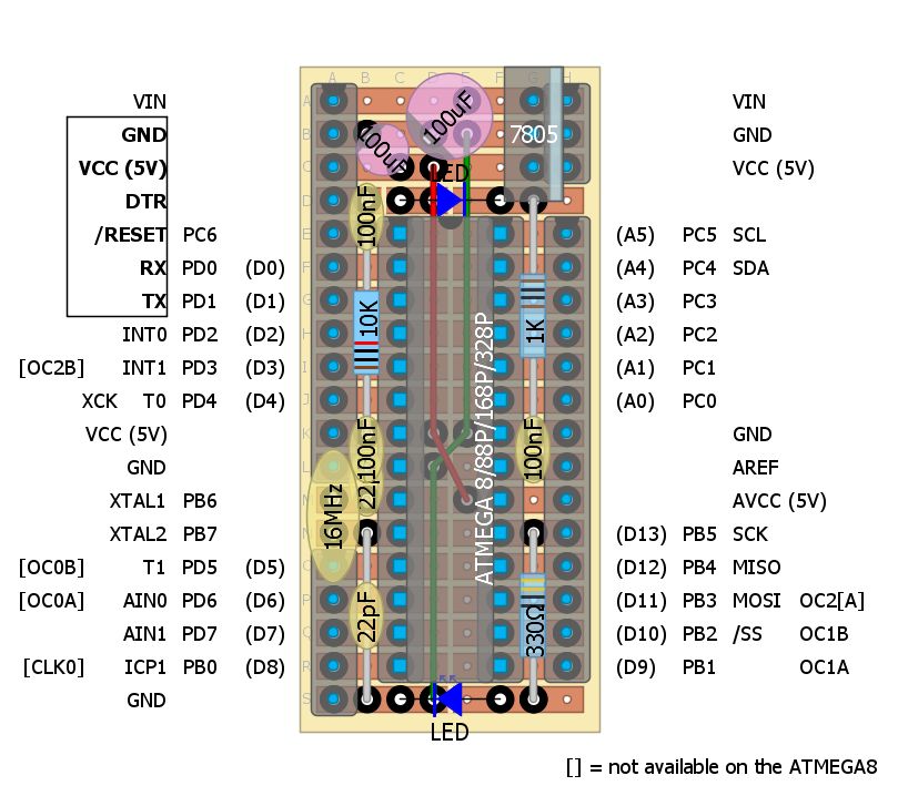
Note: DIY Layout Creator was used to produce this design
> https://code.google.com/p/diy-layout-creator/
Step 2: Prepare the stripboard for soldering
Using a utility knife cut the copper traces as indicated.
Keep in mind the board will be a mirror image when you flip it over.
I find it easiest to first score the board trying to just barely cut through the copper. Then, I angle the knife a bit (to cut a v-groove) and proceed to make the cut deeper from both sides.
Be careful so that you leave enough copper to solder the holes on either side of any cut, while ensuring that enough copper is removed to ensure the copper is truly separated from either side and won’t bridge when soldered.
Step 3: Solder the ground and positive voltage wires
1. Cut the ground and positive voltage wires to length and strip the ends.
I use the wire from an old RJ45 network cable. Make sure the wire is solid and not stranded.
2. Place the wires into the stripboard as indicated.
You may find it difficult to get two wires into one hole. I find that taking a mini needle-nose pliers and mashing on the ends of both wires a bit helps.
3. Double check that the wire placement matches the design and that the metal in the wires are not touching each other.
4. Finally, flip the board over and solder the wires in place.
Step 4: Solder the DIP IC socket
Place the DIP IC socket (or 2x 14-pin DIP/SIP socket adapters) and solder them in place.
Step 5: Solder the resistors and ceramic capacitors
1. Bend the leads of each component based on the distance it will need to span.
Note: A easy to build bender jig made from a spare piece of protoboard can come in handy here (see picture).
2. Place each component into the stripboard in the appropriate location. Pay careful attention to the components that share a hole.
3. Double check that each component is properly placed according to the diagram.
4. Proceed to solder each component and clip the leads to a reasonable length.
Step 6: Solder the LEDs and Capacitors
1. Place the LEDs and electrolytic capacitors according to the diagram.
Note: LEDs and electrolytic capacitors are directional and must be placed in the proper orientation.
* For LEDs, place the Cathode towards ground.
Looking inside an LED, the Cathode is usually the larger pad, but the smaller lead.
(see picture, source: http://www.societyofrobots.com/electronics_led_tutorial.shtml)
* Electrolytic capacitors should have a marking on the label (‘-‘)
which indicates which lead should be placed towards ground.
2. Double check that the LEDs and capacitors are placed properly.
3. Proceed to solder them in place and cut their leads to a reasonable length.
For more detail: YABBAS – Yet Another Bare Bones Arduino (on Stripboard)