In this project we will be developing a fun circuit using Force sensor and Arduino Uno. This circuit generates sound linearly related to force applied on the sensor. For that we are going to interface FORCE sensor with Arduino Uno. In UNO, we are going use 8 bit ADC (Analog to Digital Conversion) feature to do the job.
A FORCE sensor is a transducer which changes its resistance when pressure is applied on surface. FORCE sensor is available in different sizes and shapes. We are going to use one of the cheaper versions because we don’t need much of accuracy here. FSR400 is one of the cheapest force sensors in the market. The picture of FSR400 is shown in below figure.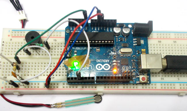
Now it is important to note that the FSR 400 is sensitive along the length, the force or weight should be concentrated on the maze on the middle of eye of sensor, as shown in figure. If the force is applied at wrong times the device could damage permanently.
Another important thing to know that, the sensor can drive currents of high range. So keep in mind the driving currents while installing. Also the sensor has a limit on force that is 10 Newtons. So we can apply only 1Kg of weight. If weights higher than 1Kg applied the sensor might show some deviations. If it’s increased more than 3Kg. the sensor might damage permanently.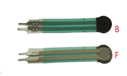 As told earlier this sensor is used to sense the changes in pressure. So when the weight is applied on top of FORCE sensor, the resistance is changed drastically. The resistance of FS400 over weight is shown in below graph,
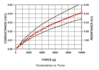
As shown in above figure, the resistance between the two contacts of sensor decreases with weight or the conductance between two contacts of sensor increases. The resistance of a pure conductor is given by:

Where,
p- Resistivity of conductor
l= Length of conductor
A= Area of conductor.
Now consider a conductor with resistance “R”, if some pressure is applied on top of conductor, the area on conductor decreases and the length of conductor increases as a result of pressure. So by formula the resistance of conductor should increase, as the resistance R is inversely proportional to area and also directly proportional to length l.
So with this for a conductor under pressure or weight the resistance of conductor increases. But this change is small compared to overall resistance. For a considerable change many conductors are stacked together. This is what happens inside the Force Sensors shown in above figure. On looking closely one can sees many lines inside the sensor. Each of these lines represents a conductor. Sensitivity of sensor is in conductor numbers.
But in this case the resistance will be decreasing with pressure because the material used here is not a pure conductor. The FSR here are robust polymer thick film (PTF) devices. So these are not pure conductor material devices. These are made up of a material, that exhibit a decrease in resistance with increase in force applied to the surface of the sensor. This material shows characteristics as shown in graph of FSR.
This change in resistance can do no good unless we can read them. The controller at hand can only read the chances in voltage and nothing less, for this we are going to use voltage divider circuit, with that we can derive the resistance change as voltage change.