Thanks to: http://jeonlab.wordpress.com/
Since I have read an article on todbot blog, I bought a couple of Wii Nunchucks from ebay. I don’t remember how much I paid for them, but it was much cheaper than buying the accelerometer breakout boards. With the nunchuck data reading library shared by todbot (Thanks!), I could easily read the accelerometer data for a Wii Nunchuck as well as the joystick and two button status.

I have thought about how to use it useful and have tested with two servos, but I had no time to proceed that project which have sit on my desk for a long time.
Recently, when I hang a picture frame on the wall at home, I got an idea to use the Wii Nunchuck more useful. That is the electronic level like a bubble level (or spirit level) using the accelerometer of the Wii Nunchuck and Arduino compatible board, JeonLab mini v1.3. Why JeonLab mini? Because 1) it is small enough to integrate into a small case; 2) once the program is loaded, the FTDI interface is not needed; and 3) since I’m going to use a small power supply, I don’t need the 5V regulator circuit. It’s a minimal Arduino, so you can easily make one on a small piece of prototype board.
What this Arduino spirit level does is to show whether the surface or edge (picture frame or a table for example) is leveled or not by displaying LEDs. If it is leveled, the central red LED is lit, otherwise the left or the right LED will turn on depending on which side it is tilted. It works similar to a bubble level, so if it tilts left the right green LED will turn on. I like this way but if you don’t like, you can modify the program and load it through the FTDI breakout board which can be plugged in at the top right corner of the JeonLab mini board as shown in the picture.
In the later steps, you will find the entire circuit diagram and Arduino codes for this project.
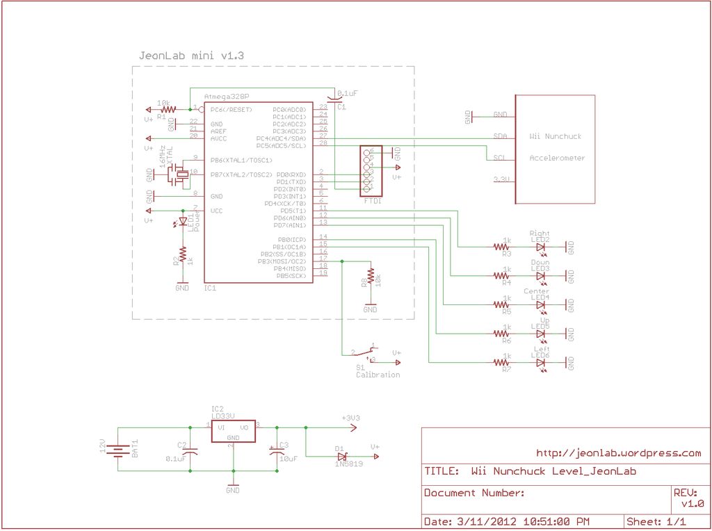
Step 1: Circuit diagram
Click on “i” button at the top left corner of the diagram for full size view.
The circuit is quite simple. There is a minimal Arduino compatible board, JeonLab mini v1.3 on the left of the diagram. As you can see, if you have an ATmega328P chip with Arduino bootloader, a 16MHz ceramic resonator, and a few resistors and capacitors can replace it. There is no built in FTDI interface so you need an external FTDI breakout board or FTDI-USB cable to load the program. But that’s not a big deal and good to reduce the whole size.
The accelerometer board is from a broken Wii Nunchuck and it can communicate via I2C interface: 3.3V, GND, data pin (SDA) to Arduino analog input pin 4, and the clock pin (SCL) to Arduino analog input pin 5.
The digital pins 5 to 9 are used to illuminate the LEDs to show which direction it is tilted. The digital pin 10 is normally pulled down through a 10k resistor and goes HIGH when the calibration switch is pressed and connect the pin to V+.
After some trials, I decided to use a 12V A23 size battery and a 3.3V regulator to provide 3.3V to both the accelerometer and the Arduino.
IMPORTANT NOTE ON THE POWER SUPPLY
The power supply I initially thought was 3.0V battery, so I thought sharing the power should be fine. BUT I forgot the program upload through the FTDI. The accelerometer chip and the I2C interface need 3.3V (3.0-3.6V) and the ATmega328 on the JeonLab mini v1.3 (and other Arduino compatible boards as well) can work at 3-5V. The Nunchuck data reading header, nunchuck_funcs.h (from WiiChuckDemo by Tod E. Kurt) provides the settings for utilizing the analog pins 3 and 2 as power source for the Nunchuck board but this provides 5V, not 3.3V. The problem is that 5V supply to the Nunchuck board could damage the chip(s) either the accelerometer or the I2C chip or both. Actually, the first one I used had gotten unstable and noisy after several times of tests, so it had to be replaced with a new one. That’s when I decided to change the power source from the 3V battery to 12V battery with a 3.3V regulator and added a Schottky diode (1N5819) to protect the Nunchuck board from FTDI 5V supply. This way, when the FTDI is connected, the 5V from a USB port ONLY powers the ATmega328P and not the accelerometer board.
Step 2: Parts
As you can see, many parts are from broken electronics. “broken” means it is just not working as it is supposed to. There are still many parts you can use for other projects.
[box color=”#985D00″ bg=”#FFF8CB” font=”verdana” fontsize=”14 ” radius=”20 ” border=”#985D12″ float=”right” head=”Major Components in Project” headbg=”#FFEB70″ headcolor=”#985D00″]Arduino
[/box]
For more detail: Wii Nunchuck Arduino Spirit Level