In this post we present the design of a scale that connects to the Internet and automatically sends weight info on a Google Document.
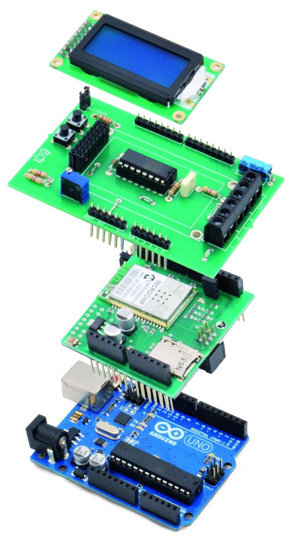
The project is composed of
- Arduino Uno board
- Wi-Fi shield
- additional shield that we used to manage data collection and I/O with a clear and comfortable and clear LCD display
- Velleman scale (or another commercial product)
Hardware
Taking a look at the diagram, we can distinguish three sections:
one for handling digital inputs (two buttons and scale’s switch),
the LCD manager
the analog signal acquisition from load cells
You may notice that P1 and P2 buttons are respectively managed by Arduino’s A3 and A4 inputs (configured as digital), while the INT switch reads the A5 signal (digital as well).
The LCD display used in our project belongs to the family of those based on HD44780 chipset, equipped with seven-pin control (RW, D4, D5, D6, D7, RS and Enable). As you can see from the diagram, RW is permanently connected to ground so it’s only operating in writing mode.
D4, D5, D6 and D7 pins are respectively managed by 3, 5, 6 and 7 digital pins of the Arduino Uno; RS is managed by pin 8 and the Enable pin from pin A0 (this configuration will also be specified in the software).
Besides the power supply (a VCC connected to 5V) and the ground (GND), the display requires a level of voltage between 0 and 5 volts to adjust the contrast in the input pin VO (adjustment made through R6 potentiometer).
Finally the display has 2 pin (A and K respectively anode and cathode) for switching on the backlight: feeding the pin with a voltage of 5V, the backlight is turned on, otherwise it is off.
The switching on and off is handled via a push-button switch that connects or disconnects the ground from the cathode.
Finally let’s analyze the part that manages the analog signal from the load cells: this is done by INA125 integrated component, a high precision amplifier developed specifically for measuring tools like scales.
The IC is fitted with two pins (6 and 7) representing the input of the differential amplification stage. These pins are connected to the two ends of the Wheatstone bridge (which in our project correspond to two of the load cell pins).
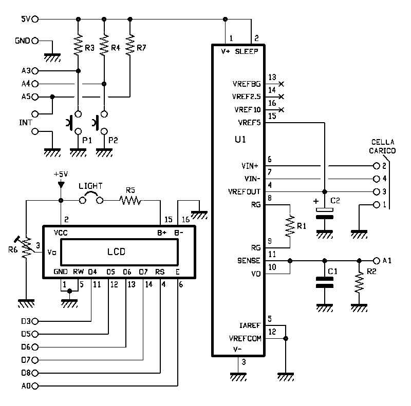
As you can figure out, the differential signal coming from the bridge has an absolute value of just a few millivolts: our project requires an amplification of about 500 times, obtained with a 120 ohm resistor.
The amplified output is provided at pins 10 and 11 of INA125; these pins are connected to A1 analog of the Arduino board, which therefore will be used for reading the value ADC.
For more detail: Wi-Fi Body Scale with Arduino Board