What follows is my proposed design for a robot. A robot with a simple design, that is easy to share and change. A robot you can build with a hand saw or a laser cutter; from cardboard or karbonite. A robot you can share; and change. This is your robot. A for the people. A robot born in the dreams of the 1980’s and realized today. A robot your children and your children’s children will look back on and say ‘that was THE ROBOT”
 But I need your help. I don’t have all the answers. I don’t even have all the questions. But maybe YOU do – so please post comments. Leave your wishes and dreams; your ‘why didn’t you… s” and ‘what if you… s’. Tell me what to build, and I will build it; then it will break; and then we will try again. And maybe, just maybe we’ll get it right.
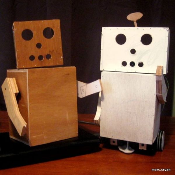
To this end I humbly submit to you — Wendell — Wendell the Robot.
Wendell is like a baby, silly and small, with a big head, tiny legs, and often, a funny smell. It is not the end but the beginning. An affirmation that says ‘I can make that; I can make that BETTER!
(too much?)
Also – I’m submitting this to the shop-bot contest – I would us it to build robots
– VOTE FOR ROBOTS –
-Also – If you want me to make you one or send you all the pieces – check out my kickstart project:
http://www.kickstarter.com/projects/marc-cryan/build-wendell-the-robot-simple-and-open-first-50-u
PROGRESS UPDATE: 12/21/2011
Working on a Robot Zombie Dance based on the “thriller dance”. A little tough without a waist, legs, or elbows. Check out the video bellow…. but don’t get to excited.
Also – built a version with a smaller head and some shoulders.
Step 1: Let’s begin
So – all rabble rousing aside. Here are the basic parameters:
- Simple to build and easy to share.
- All designs created using freely available software
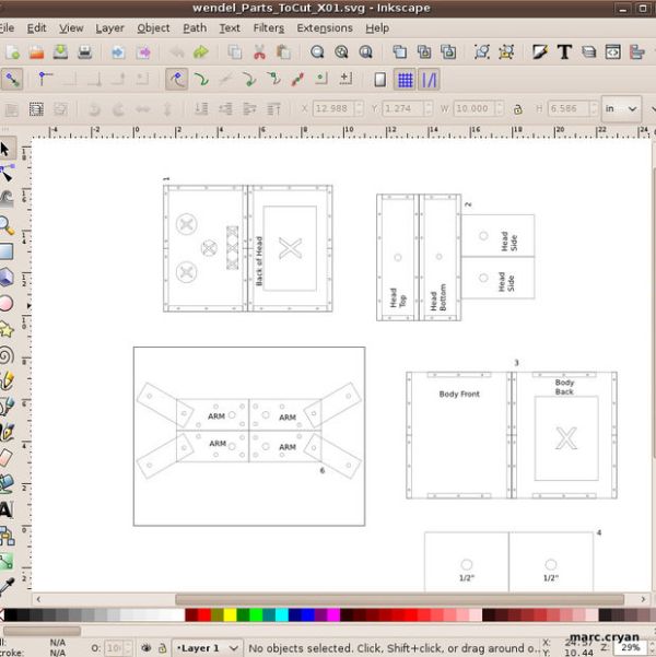
- Scallable Vector Graphics are preferred.
- Open source electronics and software
- Arduino based microelectronics
- Arduino and Processing development enviroment
- Simple motors and mechanics
- Simple sensors
Note: an alternate ‘skinny, small head’ version is attached to this step. (next step has original files – big head, fat)
Step 2: Print design and stick to plywood
-Print PDFs and glue to 1/4 in plywood using an adhesive spray.
-This step has the PDFs and the SVG (inkscape) files
Step 3: Cut out the parts
All the cuts are straight, so you should be able to use whatever saw you have around.
I am m using a small band saw with a thin blade.
Step 4: Drill the holes
Drill out all holes
-I’m using a drill press but a hand drill would be fine.
Brad-tip bits make a nice cut and are easy to position. For the 1″
holes
I am using a fostner bit – generally, good bits are worth buying.
-The small holes are denoted with stars. Pre-drill these with a small
bit, this is 1/16th”. These are pilot holes for the brad nails, so make
sure your drill bit is smaller than the nail. Using a drill press you
can set the depth so it just touches the bottom of the hole; this leaves
a little wood to grab the tip of the nail as you are working.
Step 5: Note about drill presses
Speed and torque are changed by moving a belt.
Kepping everything in the middle is fine, but you will get better and faster cuts if you use the higher speed for small holes (belt is all the way up – big to little). Lower speed for the big holes (little to big pulley)
Step 6: Cut out the slots and big areas
The slots and big cutouts are a pain to do by hand. Hopefully we can get eliminate these from the design.
Drill out as much material as possible, then clean up the edges with knife or chisel. Try not to get blood on the parts.
Step 7: Layout the pieces
The pieces are labeled to help guide assembly.
I find it useful to lay all the pieces out, as if you where unfolding a box.
Step 8: Assemble the body
-Assemble to pieces starting from the front (face) and work towards the
back. By starting with the most visible part of the robot, you can move
any gaps are mistakes to the back.
Leave the back of the head and body open for now.
Step 9: Assemble arms
-Each arm is made of two parts – for this version you can just tape them
together. You could also put standoffs between the peices which would
leave a gap for motors and wires.-Attach the servo armature to the robot arm. Using brad nails, attach the servo arms to the inside of the
robot arms. Line up the holes.
Step 10: About Servo Motors
- Small, medium, large
- Continuous or 180deg rotation
- Attachments
Wiring:
Hobby servos are easy to wire.
Black/brown to ground
Red to Vin
Yellow/orange to a digital PWM pin
You can tie together all the ground wires and all the Vins.
But the PWM lines have to each go to a separate pin.
Step 11: Programming
The arduino servo library makes these motors simple to work
with. You just tell the servo an angle and it does it.
For more detail: Wendell the Robot