This is a very interesting project in which we are going to learn how to implement virtual reality using Arduino and Processing. For most of us, the movie Iron man by Jon Favreau has always been an inspiration to build new things that will make our life easy and more fun. I have personally admired the Techs that are shown in the movie and have always wanted to build something similar to that. So, in this project I have tried to mimic the Virtual reality stuffs that happen in the movie, like we can simply wave our hand in front of the computer and move the pointer to the desired location and perform some tasks.
Here I will show you how you can simply wave your hand in front of webcam and draw something on your computer. I will also show you how you can toggle lights by virtually moving your hand and making clicks with your fingers in the air.
Concept:
To make this happen we have to leverage the power of Arduino and Processing combined. Most of would be familiar with Arduino, but Processing might be new for you. Processing is an application just like Arduino and it is also Open source and free to download. Using Processing you can create simple system applications, Android applications and much more. It also has the ability to do Image Processing and Voice recognition. It is just like Arduino and is much easy to learn, but do not worry if you are completely new to processing because I have written this tutorial fairly simple so that anyone with interest can make this working in no time.
In this tutorial we are using Processing to create a simple System application which provides us an UI and track the position of our hand using Image processing. Now, we have to make left click and right click using our fingers. To make that happen I have used two hall sensors (one on my index finger and the other on middle finger) which will be read by the Arduino Nano. The Arduino also transmits the click status to the Computer wirelessly via Bluetooth.
It might sound complicated but, Trust me; it is not as hard as it sounds. So let us take a look at the materials needed for this project to be up and running.
Materials Required:
- Arduino Nano
- Hall sensor (A3144) – 2Nos
- A small piece of magnet
- Bluetooth Module (HC-05/HC-06)
- 9V battery
- Connecting Wires Dot board.
- A pair of gloves
- Arduino IDE (Software)
- Processing IDE(Software)
- A Computer with Webcam and Bluetooth (you can also use external Bluetooth or Webcam for your computer)
Schematics and Hardware:
The hardware part of this project is very simple and easy to build. The complete schematic is shown below.
The Arduino, resistors and the berg stick pins are soldered onto a dot board as shown below.
The hall sensor and the Bluetooth module is soldered to a connector wire as shown below.
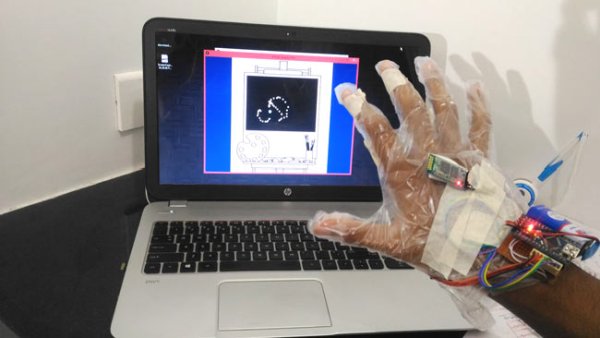
Once these two sections are ready it can be assembled onto gloves so that it is easy to use. I have used disposable plastic gloves which can be purchased from any medical shop near you. You should make sure that the magnet comes on your thumb finger and the hall sensor 1 and hall sensor 2 should be present before your index and middle finger respectively. I have used duck tapes to secure the components in place. Once the components are assembled it should look something like this.
Now let us open the Arduino IDE and start programming.
Program for Arduino:
The purpose of this Arduino code is it to read the status of the hall sensor and broadcast them using the Bluetooth module. It should also receive data from Bluetooth and toggle the onboard LED based on the incoming value. The complete program is given at the end of this tutorial; I have also explained few lines below.
if (Phs1!=HallState_1 || Phs2!=HallState_2) //Check if new keys are pressed
 {
if (HallState_1==LOW && HallState_2==LOW)
Aisha.write(1);
if (HallState_1==HIGH && HallState_2==LOW)
Aisha.write(2);
if (HallState_1==LOW && HallState_2==HIGH)
Aisha.write(3);
if (HallState_1==HIGH && HallState_2==HIGH)
Aisha.write(4);
 }
As shown in the above lines based on the status of the hall sensor the Bluetooth will write a particular value. For example if hall sensor 1 is high and hall sensor 2 is low, then we will broadcast the vale “2” via the Bluetooth module. Make sure you write the values to the BT module and not print them. Because it will be easy to read the only on Processing side only if they are written. Also the value will only send if it is not as same as the previous value.
if (BluetoothData=='y')
digitalWrite(ledpin,HIGH);
if (BluetoothData=='n')
digitalWrite(ledpin,LOW);
These lines are used to toggle the onboard LED which is connected to the Pin 13, based on the value receive by the BT module. For example if the module receives a ‘y’ then the LED is turned on and if it receives an ‘n’ then it is turned off.
Program for processing:
The purpose of the Processing program is to create a system application which can act as an UI (User interface) and also perform image processing to track a particular object. In this case we track the blue object that we stuck to our gloves above. The program basically has four screens.
- Calibration Screen
- Main Screen
- Paint Screen
- LED toggle Screen
We can navigate from one screen to another by simply waving our hands and dragging screens on air. We can also make clicks on desired places to toggle LED or even draw something on screen.
You can copy paste the complete Processing program (given at the end) and modify it based on your creativity or simple download the EXE files from here, and follow the following steps to launch the application.
- Install JAVA in your computer if you have not installed it before
- Install You Cam perfect on your computer
- Power up your Arduino and pair your Computer with the Bluetooth Module
- Launch the application file
If everything goes fine you should be able to notice the LED on your Bluetooth module getting stable and your webcam light going ON. If you have any problems reach me through the comment section and I will help you out.
Watch the video at the end to know how to calibrate your application and use it.
If you want to modify the code and build more features into this then you can use the following insights of the program
The processing IDE can be downloaded from here. If you want to learn more about processing and create more interesting projects then you can visit the tutorials here.
Processing has the ability to read Serial data, in this program the serial data is comes from the Bluetooth COM port. You have to select which COM port your Bluetooth is connect to by using this line below
port = new Serial(this,Serial.list()[1],9600);
Here I have selected my 1st COM port which is COM5 in my case (see image below) and I have mentioned that by Bluetooth module runs on 9600 baudrate.

As said earlier processing also has the ability to do image processing, in this tutorial the images are sent inside the sketch using a webcam. In each image we track for a particular object. To know more about this you can visit this tutorial.
I have tried my best to explain the program (given at the end) through the comment lines. You can download the files here.
If you want to know more about the sketch you can reach me through the comment section and I will help you out.
Working:
Once the Hardware and software is ready, wear the gloves and get ready for some action. Now, simply power the Arduino and then launch the Application. The led on the Bluetooth module should go stable. Now it means that your System application has established a Bluetooth link with your Arduino.
You will get the following screen where you have to select the object to be tracked. This tracing can be simply done by clicking on the object. In this case the object is the Blue disc. Now you can move your object and notice that the pointer follows your object. Use a unique colour object and a bright room for best results.
Now touch your thumb finger with index finger and you should see the message “Key 1 Pressed” and the when you press your thumb with middle finger you should see “Key 2 Pressed” this indicates that everything works fine and the calibration is over. Now click on the Done button.
Read more: Virtual Reality using Arduino and Processing