Hardware
Controller
The Arduino platform is selected for this project, mainly due to its open software and hardware nature which has resulted in availability of extensive technical information. As a result there are many tutorials and example project available for this platform. A list of arduino boards can be found here. Many of these boards including Arduino Uno and Arduino Mega are perfectly capable of flying a quad copter. In this project, the Arduino compatible Seeeduino board is used; specifically, Seeeduino Mega v1.1 mainly since it was available at hand. This was an intentional design constraint based on the purpose of this project as a test run for a future class offering of the mechatronics class – to use a different controller would obsolete much of the hardware available for the class.

Brushless Motor
Many electric devices such as blow dryer and CPU fan use brushed direct current (DC) motors. They are called brushed since they use a carbon brush to keep the current flowing into the rotating section (called shaft or rotor) inside the motor. We use four brushless DC motors, specifically this motor. 10g brushless Brushless motors are more suitable for this project since they deliver much higher revolutions per minute (RPM). Since they dont use brush to deliver current to the shaft, there is much less friction; therefore, they are much more efficient and can produce more torque. There is some variation between motors, following some advice on the internet we ordered an extra one and were glad we did. The speed variation was annoying, but the benefit really came out in one of the crashes!
Electronic Speed Controller (ESC)
Four Turnigy plush 6amp brushless speed controllers (Plush 6A) are used in this project. Plush 6A
Direction of rotation
The three wires from brushless motor can be connected to the three output wires of the speed controller in any order. However, reversing the direction of rotation of the motor is done by switching any two of these three wires. Therefore, it is a good idea to find a right order by temporary connecting the wires and checking the rotation of motor. The input signal to the brushless motor only defines the power at which the motor should operate or its RPM, but not the direction. The signal that is needed by the ESC is equivalent to that of a servo motor. Therefore the servo library can be used to operate an ESC using an arduino board. The image below shows the characteristics of this input signal to the ESC as captured by an oscilloscope while the brushless motor is operating with 70 percent power.
Quadcopter Build Log
This document captures all the relevant efforts that were made in construction of this quadcopter. The timeframe of the project is January 2011 to April2011.
Hardware
Controller
The Arduino platform is selected for this project, mainly due to its open software and hardware nature which has resulted in availability of extensive technical information. As a result there are many tutorials and example project available for this platform. A list of arduino boards can be found here. Many of these boards including Arduino Uno and Arduino Mega are perfectly capable of flying a quad copter. In this project, the Arduino compatible Seeeduino board is used; specifically, Seeeduino Mega v1.1 mainly since it was available at hand. This was an intentional design constraint based on the purpose of this project as a test run for a future class offering of the mechatronics class – to use a different controller would obsolete much of the hardware available for the class.
Brushless Motor
Many electric devices such as blow dryer and CPU fan use brushed direct current (DC) motors. They are called brushed since they use a carbon brush to keep the current flowing into the rotating section (called shaft or rotor) inside the motor. We use four brushless DC motors, specifically this motor. 10g brushless Brushless motors are more suitable for this project since they deliver much higher revolutions per minute (RPM). Since they dont use brush to deliver current to the shaft, there is much less friction; therefore, they are much more efficient and can produce more torque. There is some variation between motors, following some advice on the internet we ordered an extra one and were glad we did. The speed variation was annoying, but the benefit really came out in one of the crashes!
Electronic Speed Controller (ESC)
Four Turnigy plush 6amp brushless speed controllers (Plush 6A) are used in this project. Plush 6A
Direction of rotation
The three wires from brushless motor can be connected to the three output wires of the speed controller in any order. However, reversing the direction of rotation of the motor is done by switching any two of these three wires. Therefore, it is a good idea to find a right order by temporary connecting the wires and checking the rotation of motor. The input signal to the brushless motor only defines the power at which the motor should operate or its RPM, but not the direction. The signal that is needed by the ESC is equivalent to that of a servo motor. Therefore the servo library can be used to operate an ESC using an arduino board. The image below shows the characteristics of this input signal to the ESC as captured by an oscilloscope while the brushless motor is operating with 70 percent power
The video below shows a simple test of driving a brushless motor with an ESC.
Propeller (Prop)
The initial propeller attempt was a 4.5×4.5E two bladed propeller. This is well below the motor specification size recommended on the website of the supplier, which called for a 7x5E propeller. The motors would not even spin this large propeller, though, so it can only be concluded that the website specification is incorrect. The propeller tests were completed by attaching the airframe and motors to a weight, and placing this weight on a scale. The weight used was approximately the diameter of the arduino board, so airflow characteristics should be comparable to those during flight. The initial weight of the airframe, motors, arduino, ESCs, battery monitor, plus the weight, was 1763g. This was well above what the motors could be expected to lift, so the total lift was calculated as the difference between initial weight (with the motors stopped) and final weight (with the motors at full power.)
Quadcopter Build Log
This document captures all the relevant efforts that were made in construction of this quadcopter. The timeframe of the project is January 2011 to April2011.
Hardware
Controller
The Arduino platform is selected for this project, mainly due to its open software and hardware nature which has resulted in availability of extensive technical information. As a result there are many tutorials and example project available for this platform. A list of arduino boards can be found here. Many of these boards including Arduino Uno and Arduino Mega are perfectly capable of flying a quad copter. In this project, the Arduino compatible Seeeduino board is used; specifically, Seeeduino Mega v1.1 mainly since it was available at hand. This was an intentional design constraint based on the purpose of this project as a test run for a future class offering of the mechatronics class – to use a different controller would obsolete much of the hardware available for the class.
Brushless Motor
Many electric devices such as blow dryer and CPU fan use brushed direct current (DC) motors. They are called brushed since they use a carbon brush to keep the current flowing into the rotating section (called shaft or rotor) inside the motor. We use four brushless DC motors, specifically this motor. 10g brushless Brushless motors are more suitable for this project since they deliver much higher revolutions per minute (RPM). Since they dont use brush to deliver current to the shaft, there is much less friction; therefore, they are much more efficient and can produce more torque. There is some variation between motors, following some advice on the internet we ordered an extra one and were glad we did. The speed variation was annoying, but the benefit really came out in one of the crashes!
Electronic Speed Controller (ESC)
Four Turnigy plush 6amp brushless speed controllers (Plush 6A) are used in this project. Plush 6A
Direction of rotation
The three wires from brushless motor can be connected to the three output wires of the speed controller in any order. However, reversing the direction of rotation of the motor is done by switching any two of these three wires. Therefore, it is a good idea to find a right order by temporary connecting the wires and checking the rotation of motor. The input signal to the brushless motor only defines the power at which the motor should operate or its RPM, but not the direction. The signal that is needed by the ESC is equivalent to that of a servo motor. Therefore the servo library can be used to operate an ESC using an arduino board. The image below shows the characteristics of this input signal to the ESC as captured by an oscilloscope while the brushless motor is operating with 70 percent power.
Propeller (Prop)
The initial propeller attempt was a 4.5×4.5E two bladed propeller. This is well below the motor specification size recommended on the website of the supplier, which called for a 7x5E propeller. The motors would not even spin this large propeller, though, so it can only be concluded that the website specification is incorrect. The propeller tests were completed by attaching the airframe and motors to a weight, and placing this weight on a scale. The weight used was approximately the diameter of the arduino board, so airflow characteristics should be comparable to those during flight. The initial weight of the airframe, motors, arduino, ESCs, battery monitor, plus the weight, was 1763g. This was well above what the motors could be expected to lift, so the total lift was calculated as the difference between initial weight (with the motors stopped) and final weight (with the motors at full power.)
Initial weight at 4.5×4.5E 1763g final weight 1400g for a total thrust of 363g. This quickly falls off as the battery drains, so subsequent tests are to be completed only on a fully charged battery.
For additional test propellers, in most cases there is only a single propeller available. It is not feasible to run only one motor, because the tether to the weight is fixed and a single motor does not provide lift as much as it simply changes the balance and threatens to topple the weight. To address this, additional propeller tests are accomplished by means of running two opposing motors, but with only one new propeller attached. Since the difference in thrust of a propeller change will be a fractional proportion of the total lift, the lowest final weight will be presumed to be the propeller with most lift. First, the original 4.5×4.5E propellers are run in this configuration. Initial weight at 4.5×4.5E 1763g final weight, two motors 1547g thrust = 216g
Next, one of the propeller was replaced with a 8×4.5E two bladed propeller.
* PROBLEM* one of the 8×4.5 props is contra-rotating! It pushes down. Had to try the other prop.
Initial weight 1765g final weight 1532g thrust = 233g
Not that much benefit and we can’t actually use 4 8 inch props on the current frame because they will interfere with each other.
Next, one propeller was replaced with a 3 bladed 5 inch with less pitch (labelled GWS EP-5030×3)
initial weight 1762g final weight 1515g thrust = 247g
Next the orange 6 inch propeller was run (GWS EP-6030) initial weight 1766g final weight 1530g thrust = 236g Of course, there is a confound between prop size and pitch. It is unknown what a 4.5 pitch 6 inch prop would do, and since the specification cannot be trusted, it is unclear which is preferred by this motor.
Finally, the GWS EP-4025 was run.
Initial weight 1765g final weight 1536g thrust = 229g
The 5 inch 3-blade propeller seems to be the best performer for the size. The shallower pitch also seems to be an advantage. It is possible that these motors simply do not have sufficient torque to drive a higher pitch propeller.
Final Configuration
Four 3 bladed 5 inch props with a 3.0 inch pitch. Model GWS EP-5030×3
Initial weight 1758g
final weight 1290g
(first pulse, quickly drops to around 1370g sustained)
thrust = 468g (peak) 388g (sustained)
The goal is to get to lift capability with a maximum of 90% of motor thrust for a sustained period so that the remaining 10% of capacity can be used for manoeuvring. This will be documented in the battery section.
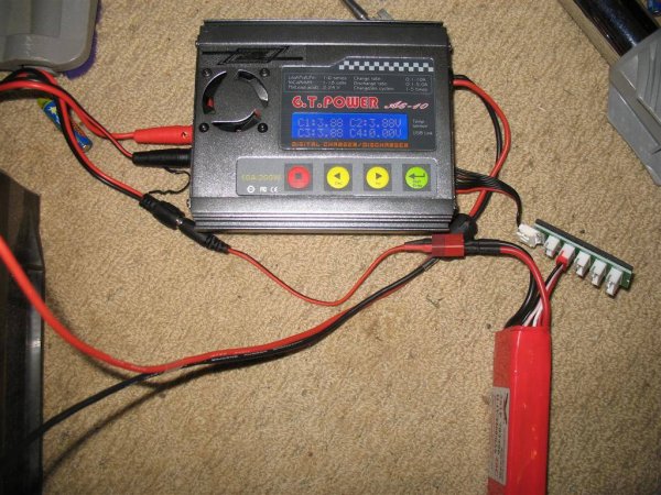
Battery
A Rhino 610mAh 3S 11.1v 20C Lipoly Pack is used that was purchased from hobby king.
Battery Monitor
To monitor the state of battery during flight and avoid accidents that may be caused by running out of battery in the middle of a flight (as well as battery damage due to overdischarge), a battery monitor is necessary. A Hobby King Battery Monitor 3S is used for this purpose. The battery monitor lights blue when it recieved above 11,0V, at 10,0-11,0V it blinks blue, under 10,0V it lights red, and when below 9,8V it beeps and blinks red.
Running Time
With the 5 in. 3 blade propellers, a trial was made with the motors at 90% capacity. At this rate of discharge it takes 9 minutes to go from a full charge to a sustained low battery warning from the battery monitor. During that 9 minutes, the 90% motor lift capacity drops from 288g to 243g.
Recharge of the batteries from a full discharge at 1.6A takes approximately 30 minutes.
For more detail: UVic Quadcopter