Note: to see everything on one page, please go to: www.tweetingcatdoor.com
After receiving many emails requesting Instructions and Kits for building the “Tweeting Cat Door “, I decided to make a version that is stand-alone and doesn’t need a computer to be run and that is easy to be put together by anyone with a soldering iron and a little time on hand. All the software is available to download, but feel free to modify it to make it better or to better suit your needs.
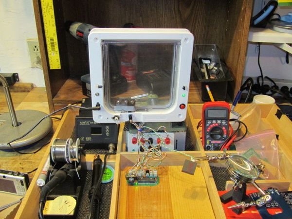
The Tweeting Cat Door works as follows:
When a pet tries to enter the pet door, a RFID reader will read the RFID tag that your pet has on the collar. If the tag is authorized , the latch of the pet door will open, a picture is taken of the pet, and uploaded to Twitter along with a funny random message, for example: “Penny is in playing with a ball of yarn.”
The pet door works in the same way when the pet tries to go out. A picture is taken and uploaded to Twitter along with a message, for example: “Gus is out to play poker with the fellas.”
The messages are chosen at random from a list of possible messages.
Here are some examples:
http://twitpic.com/2a7q32
http://twitpic.com/2uehbs
http://twitpic.com/2uc1ry
http://twitpic.com/29jcd2
Here is @GusAndPenny Sadly, there are no recent updates @gusandpenny. Gus died a while back (probably a fight with a raccoon or other cats?) and not long after, Penny followed.
Note: The twitter part of the project is optional. You can just build the Arduino controller, the latch to lock/unlock the pet door, mount the RFID reader and the latch on the door and you are ready to go. Your pets would be “sorted” by the RFID tag they are waring.
Here you’ll find detailed step by step instructions and kits with all the components (you can buy kits, PCB, preprogrammed Arduino chip, etc, by contacting me). By following the instructions on this page, you will have – in no time – your own RFID enabled, twitting pet door, just like the original Tweeting Cat Door.
How does the RFID (Radio-frequency identification) enabled pet door works?
Each pet will have a small RFID tag on the collar and the pet door will open ONLY for your pet for entering the house.
The RFID enabled pet door has 3 settings that can be controlled by pressing a button. For each setting a LED will light in a different color:
GREEN – Open, your pet is allowed to exit the door and to enter the door.
BLUE – In-only, your pet is allowed to only enter the door (for example at night when you want your pet inside)
RED – Locked, the door will stay locked and no exit or entering is allowed.
Note: The entering through the door is controlled by RFID, exiting is controlled by a infrared beam.
Step 1: Make your own!
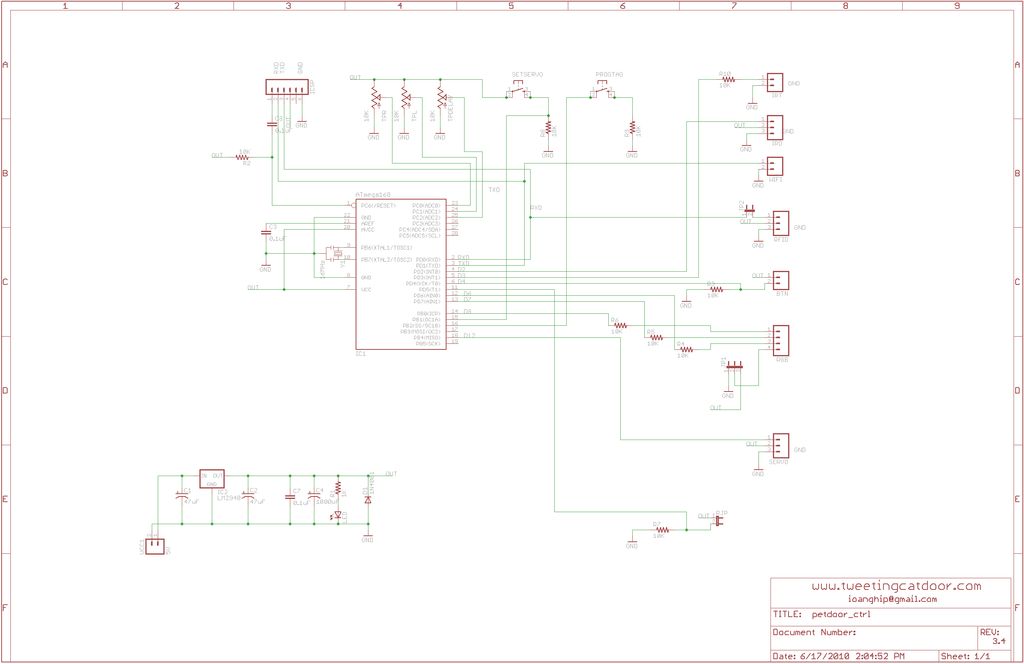
Here is the schematic for the pet door controller we will use (click on the image to zoom in).
And if you want to see the PCB board design, click on following links:
The schematic
Top Layer with Silkscreen
Top Layer
Bottom Layer
(if you want to make your own PCB board, check out this)
You can also download the Eagle files at the bottom of this page.
On the schematic, you will see a bunch of header connectors, here is the description for each of them:
VCC1 : connect the power supply here
ICSP : you will use this for uploading your software to the Arduino chip.
IRT : the Infrared transmiter LED goes here
IRD : the infrared detector
WIFI : serial connection that goes to the OpenWrt router
RFID : your RFID reader (the software supports both ID12 and Parallax readers, selectable from RJP)
BTN : button to control the way the door operates (open, in only, locked)
RGB : RGB LED (common anode, common cathode, both work, selectable from JP1)
SERVO : the servo that will open/close the pet door latch
SETSERVO button : when pressed you are going to be able to set the max values the servo goes to right or left. The settings are made using the trimpots TPR (max right) and TPL (max left).
PROGTAG button : when pressed, arduino will switch in “learning mode” and you can program new RFID tags. The tags are “learned” by passing them in front of the reader.
JP2: disconnects the RFID reader from the serial, and this way the ICSP can be used to reprogram arduino chip.
 petdoor3.4.zip86 KB
Step 2: Parts List
Here is the list of all the parts you are going to need for this project:
Semiconductors:
1x ATMEGA328P-PU 28 pin DIP package with Arduino bootloader
1x LM7805 LDO TO-220 package
1x 1N400x Diode
1x 3mm LED (red or green)
1x 16 MHZ ceramic resonator (built-in capacitors)
1x RGB LED
1x PNA4602M 38KHz Infrared Detector
[box color=”#985D00″ bg=”#FFF8CB” font=”verdana” fontsize=”14 ” radius=”20 ” border=”#985D12″ float=”right” head=”Major Components in Project” headbg=”#FFEB70″ headcolor=”#985D00″]1x ATMEGA328P-PU 28 pin DIP package with Arduino bootloader
1x LM7805 LDO TO-220 package
1x 1N400x Diode[/box]
For more detail: Tweeting Cat Door using an Arduino