Use the Maxim MAX7219 LED display driver with Arduino in Chapter 56 of our Arduino Tutorials. The first chapter is here, the complete series is detailed here.
Update – 4/1/15 – This article is pending a re-write, please refrain from comments and questions until the new version is published.
Introduction
Sooner or later Arduino enthusiasts and beginners alike will come across the MAX7219 IC. And for good reason, it’s a simple and somewhat inexpensive method of controlling 64 LEDs in either matrix or numeric display form. Furthermore they can be chained together to control two or more units for even more LEDs. Overall – they’re a lot of fun and can also be quite useful, so let’s get started.
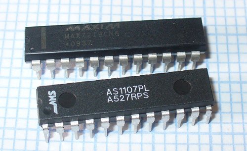
Here’s an example of a MAX7219 and another IC which is a functional equivalent, the AS1107 from Austria Microsystems. You might not see the AS1107 around much, but it can be cheaper – so don’t be afraid to use that instead:
When shopping for MAX7219s you may notice the wild price fluctuations between various sellers. We’ve researched that and have a separate article for your consideration.
 At first glance you may think that it takes a lot of real estate, but it saves some as well. As mentioned earlier, the MAX7219 can completely control 64 individual LEDs – including maintaining equal brightness, and allowing you to adjust the brightness of the LEDs either with hardware or software (or both). It can refresh the LEDs at around 800 Hz, so no more flickering, uneven LED displays.
You can even switch the display off for power saving mode, and still send it data while it is off. And another good thing – when powered up, it keeps the LEDs off, so no wacky displays for the first seconds of operation. For more technical information, here is the data sheet: MAX7219.pdf. Now to put it to work for us – we’ll demonstrate using one or more 8 x 8 LED matrix displays, as well as 8 digits of 7-segment LED numbers.
Before continuing, download and install the LedControl Arduino library as it is essential for using the MAX7219.
Controlling LED matrix displays with the MAX7219
First of all, let’s examine the hardware side of things. Here is the pinout diagram for the MAX7219:
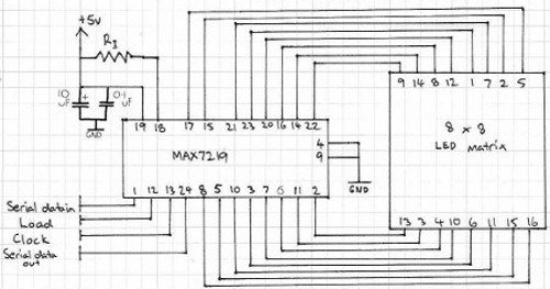
The MAX7219 drives eight LEDs at a time, and by rapidly switching banks of eight your eyes don’t see the changes. Wiring up a matrix is very simple – if you have a common matrix with the following schematic:
connect the MAX7219 pins labelled DP, A~F to the row pins respectively, and the MAX7219 pins labelled DIG0~7 to the column pins respectively. A total example circuit with the above matrix is as follows:
The circuit is quite straight forward, except we have a resistor between 5V and MAX7219 pin 18. The MAX7219 is a constant-current LED driver, and the value of the resistor is used to set the current flow to the LEDs. Have a look at table eleven on page eleven of the data sheet:
You’ll need to know the voltage and forward current for your LED matrix or numeric display, then match the value on the table. E.g. if you have a 2V 20 mA LED, your resistor value will be 28kΩ (the values are in kΩ). Finally, the MAX7219 serial in, load and clock pins will go to Arduino digital pins which are specified in the sketch. We’ll get to that in the moment, but before that let’s return to the matrix modules. In the last few months there has been a proliferation of inexpensive kits that contain a MAX7219 or equivalent, and an LED matrix. These are great for experimenting with and can save you a lot of work.
At the top is an example from ebay, and the pair on the bottom are the units from a recent kit review. We’ll use these for our demonstrations as well.
Now for the sketch. You need the following two lines at the beginning of the sketch:
|
1
2
|
#include “LedControl.h”
LedControl lc=LedControl(12,11,10,1);
|
The first pulls in the library, and the second line sets up an instance to control. The four parameters are as follows:
- the digital pin connected to pin 1 of the MAX7219 (“data in”)
- the digital pin connected to pin 13 of the MAX7219 (“CLK or clock”)
- the digital pin connected to pin 12 of the MAX7219 (“LOAD”)
- The number of MAX7219s connected.
If you have more than one MAX7219, connect the DOUT (“data out”) pin of the first MAX7219 to pin 1 of the second, and so on. However the CLK and LOAD pins are all connected in parallel and then back to the Arduino.
Next, two more vital functions that you’d normally put in void setup():
|
1
2
|
lc.shutdown(0,false);
lc.setIntensity(0,8);
|
The first line above turns the LEDs connected to the MAX7219 on. If you set TRUE, you can send data to the MAX7219 but the LEDs will stay off. The second line adjusts the brightness of the LEDs in sixteen stages. For both of those functions (and all others from the LedControl) the first parameter is the number of the MAX7219 connected. If you have one, the parameter is zero… for two MAX7219s, it’s 1 and so on.
Finally, to turn an individual LED in the matrix on or off, use:
|
1
|
lc.setLed(0,col,row,true);
|
which turns on an LED positioned at col, row connected to MAX7219 #1. Change TRUE to FALSE to turn it off. These functions are demonstrated in the following sketch:
|
1
2
3
4
5
6
7
8
9
10
11
12
13
14
15
16
17
18
19
20
21
22
23
24
25
26
27
28
29
30
31
32
33
34
35
|
#include “LedControl.h” // need the library
LedControl lc=LedControl(12,11,10,1); //
// pin 12 is connected to the MAX7219 pin 1
// pin 11 is connected to the CLK pin 13
// pin 10 is connected to LOAD pin 12
// 1 as we are only using 1 MAX7219
void setup()
{
// the zero refers to the MAX7219 number, it is zero for 1 chip
lc.shutdown(0,false);// turn off power saving, enables display
lc.setIntensity(0,8);// sets brightness (0~15 possible values)
lc.clearDisplay(0);// clear screen
}
void loop()
{
for (int row=0; row<8; row++)
{
for (int col=0; col<8; col++)
{
lc.setLed(0,col,row,true); // turns on LED at col, row
delay(25);
}
}
for (int row=0; row<8; row++)
{
for (int col=0; col<8; col++)
{
lc.setLed(0,col,row,false); // turns off LED at col, row
delay(25);
}
}
}
|
And a quick video of the results:
How about controlling two MAX7219s? Or more? The hardware modifications are easy – connect the serial data out pin from your first MAX7219 to the data in pin on the second (and so on), and the LOAD and CLOCK pins from the first MAX7219 connect to the second (and so on). You will of course still need the 5V, GND, resistor, capacitors etc. for the second and subsequent MAX7219.
You will also need to make a few changes in your sketch. The first is to tell it how many MAX7219s you’re using in the following line:
|
1
|
LedControl lc=LedControl(12,11,10,X);
|
by replacing X with the quantity. Then whenever you’re using a MAX7219 function, replace the (previously used) zero with the number of the MAX7219 you wish to address. They are numbered from zero upwards, with the MAX7219 directly connected to the Arduino as unit zero, then one etc. To demonstrate this, we replicate the previous example but with two MAX7219s:
|
1
2
3
4
5
6
7
8
9
10
11
12
13
14
15
16
17
18
19
20
21
22
23
24
25
26
27
28
29
30
31
32
33
34
35
36
37
38
39
40
41
|
#include “LedControl.h” // need the library
LedControl lc=LedControl(12,11,10,2); //
// pin 12 is connected to the MAX7219 pin 1
// pin 11 is connected to the CLK pin 13
// pin 10 is connected to LOAD pin 12
// 1 as we are only using 1 MAX7219
void setup()
{
lc.shutdown(0,false);// turn off power saving, enables display
lc.setIntensity(0,8);// sets brightness (0~15 possible values)
lc.clearDisplay(0);// clear screen
lc.shutdown(1,false);// turn off power saving, enables display
lc.setIntensity(1,8);// sets brightness (0~15 possible values)
lc.clearDisplay(1);// clear screen
}
void loop()
{
for (int row=0; row<8; row++)
{
for (int col=0; col<8; col++)
{
lc.setLed(0,col,row,true); // turns on LED at col, row
lc.setLed(1,col,row,false); // turns on LED at col, row
delay(25);
}
}
for (int row=0; row<8; row++)
{
for (int col=0; col<8; col++)
{
lc.setLed(0,col,row,false); // turns off LED at col, row
lc.setLed(1,col,row,true); // turns on LED at col, row
delay(25);
}
}
}
|
And again, a quick demonstration:
Another fun use of the MAX7219 and LED matrices is to display scrolling text. For the case of simplicity we’ll use the LedControl library and the two LED matrix modules from the previous examples.
First our example sketch – it is quite long however most of this is due to defining the characters for each letter of the alphabet and so on. We’ll explain it at the other end!
For more detail: Tutorial – Arduino and the MAX7219 LED Display Driver IC