This instructable covers the assembly and use of a Tiny Wearable LED kit. The kit is useable immediately but is desigend to be hackable and can be reprogrammed to your liking using an ISP programmer or Arduino board and the Arduino IDE.
There are not too many tiny implementations of microcontrollers. The Arduino lillypad is quite large and expensive and if you want to drive a dozen LEDs you still need to multiplex them. What we could use is something small and simple that will run for an evening off a minature battery….
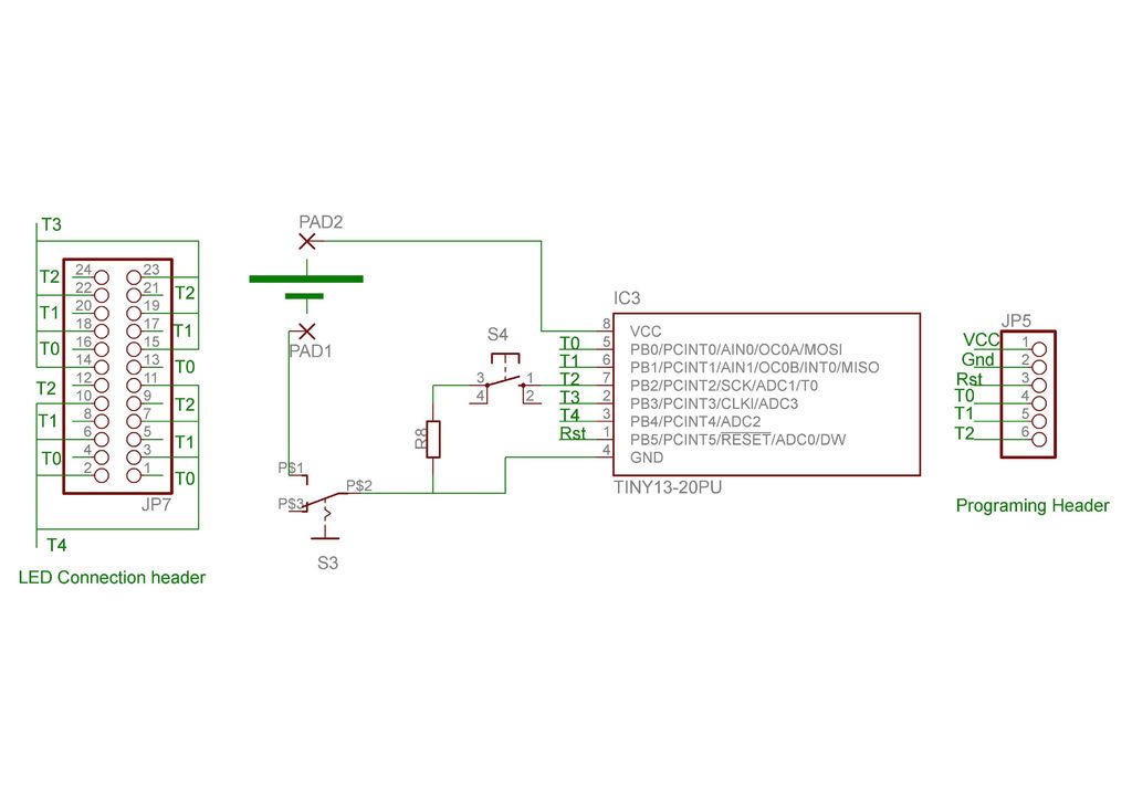
Here we are taking advantage of two key features to be able to drive 12 independent LEDs from the five programmable pins of an 8-pin ATtiny85. Firstly, the tri-state nature of the pins means that any pins not being used can be set to high-impedance (INPUT) so that they are not affected. That gives us 2 x 3 = 6 pairs of outputs. Secondly, because LEDs conduct only in one direction, we can put 2 LEDs on each pair of lines to give 12 in all.
Our ATtiny runs happily from a 3v coin cell and because we are driving our 12 LEDs in pulsed mode the overall current draw is quite low. We can therefore run our complete setup from a CR2032 coin cell for several days continuously. I haven’t tested it to exhaustion but I have run it for 48 hours continuously without any problems. That was actually off a 2025 which is lower capacity than the 2032.
You could in theory light up to 3 LEDs at the same time using this setup but I worry that the coin-cell would not handle the current so in this I limited myself to pulsing only 1 LED at a time.
Obviously, because we are driving the LEDs one at at time in pulsed mode, if we light a lot of them then they will not be as bright as direct attachment to a coin cell and wouldn’t ne hugely visible in bright sunlight. However, by lighting only a few at a time we can make some impressive looking effects, especially indoors.
This is designed to be “sewable” into clothes or could be worn as a programable badge etc.
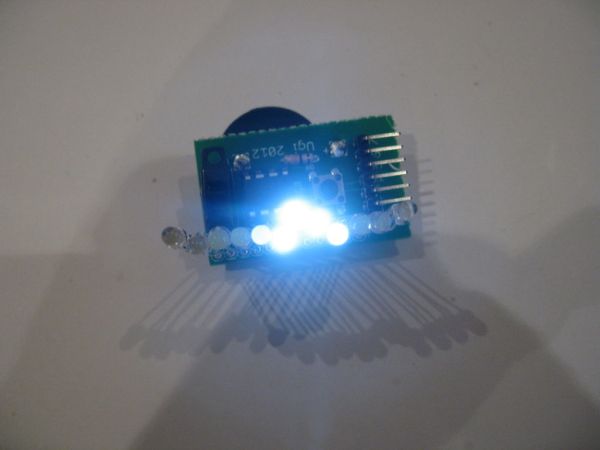
I don’t have a video of the final version but this is the prototype with the LED mounted lose on the board as a test:
Step 1: The Kit
The Kit:
Your kit should contain:
1 CR2032 Coin Cell
1 CR2032 Coin Cell Holder
1 ATtiny85 AVR microprossor (preprogrammed)
1 Sliding Power Switch
1 Tactile Mode Switch
1 PCB
1 Length of thin Stainless Steel Wire or conductive thread (I only have ss wire)
12 Ultra-bright LEDs
With such a small inventory of parts chosen to be relatively water-tollerant, it shoud be entirely feasable to wash the garment into which the kit is incorporated (remove the battery first obviously) but hand-washing would be advisable and please ensure all parts are fully dry before reinserting the battery.
Your kit does not require any programming, however, if you do wish to reprogram it, you will need the additional programming components included:
1 x 6-way 90′ male header
1 6-way female to 6 x 1-way male breakout cable.
These components should allow you to connect your Tiny Wearable LED board to your Arduino or other ISP programmer – see Step 6
Additional Materials Required:
You may find the following useful in assembling and using your kit:
Needle and thread.
Scraps of fabric and/or velcro.
5-minute epoxy, silicone or other sealant. Nail varnish is ideal for this.
Tools Required:
Soldering iron and solder
Side cutters
Small pliers.
Step 2: Populating the board
Before we start putting components down on the board, let’s have a quick look at what we’ve got:
The board is about an inch wide by less than 1.5 inches long with only five essential components to solder. The largest of these is the battery holder and since this is going on the bottom of the board we need to do that last.
Obviously the heart of our device is the ATtiny85 microprocessor, we also have a power switch (sliding switch at the top) a tactile switch for input and a current limiting resistor on that switch. Positions for the 12 LEDs are on the left of the board but typically not all of these would be needed. The connections with rings around them are the key ones
Tools Required:Soldering iron and solder
Side cutters
Small pliers.[/box]