A couple of weekends ago I was in the mood to do some retrogaming and didn’t know what I wanted to play so I asked for some suggestions from Twitter. I played some Castle Wolfenstein, Snake Byte, BC’s Quest for Tires, and Miner 2049er on the Apple IIe and then I wanted to try some games on my Apple IIgs. Unfortunately my IIgs has had intermittent issues for a long time, and it was looking like bad RAM might be the culprit.
The IIgs has an Applied Engineering GS~RAM Plus in it with 3 megabytes of RAM. The RAM is divided up into 1 meg banks, and each bank is made of eight 1M x 1 DRAM chips. I figured if I could narrow down which chip was bad I could replace it or the entire bank. There are lots of different makes of DRAM chips which are compatible, Hitachi labels theirs HM511000 & HM511001, OKI has MSM411000RS & MSM411001RS, and NEC has D421000C & D421001C. As it turned out an old ISA RAM card I got from a garage sale a year or two ago was filled with Toshiba TC511001 chips so I had plenty of spares.
My first thought was to test the chips in the TL866CS, but it doesn’t support them. What to do? Well why not build something with an Arduino to test the DRAM? I wasn’t sure how easy that would be since DRAM is trickier than SRAM because it requires a periodic refresh to keep the bits from fading. Looking around to see if anyone had done such a thing before I found this post where Len Page had done something similar using smaller 256k x 1 chips that were in his PDP 11.
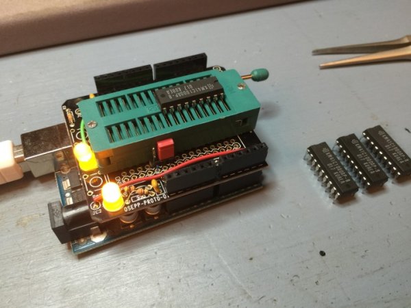
I bought a bunch of Zero Insertion Force (ZIF) sockets a while back thinking I might make some cartridge boards for my Atari 800 or Atari 2600 that would let me easily swap out an EPROM, but of course they had been sitting in one of my electronics parts bins since then. I wasn’t sure how hard it would be to wire up a ZIF socket to an Arduino but then I also discovered I had some proto shields sitting around unused.
I sketched out how I would need to wire up the DRAM chip to the arduino pins, and it actually looked pretty simple with mostly straight runs. I soldered the ZIF socket onto the shield and then used wire-wrap wire to link everything together. I was going to use regular wire but trying to strip the insulation off such short pieces of wire was a pain and by using wire-wrap wire the soldering iron would just melt the insulation off as I soldered making it very easy to solder the two ends in place and then trim the wire after.
Read more: Testing DRAM Using an Arduino