In this tutorial you can make an RFID access system. It’s very simple and can be used with a wide variety of end-uses.
Updated 18/03/2013
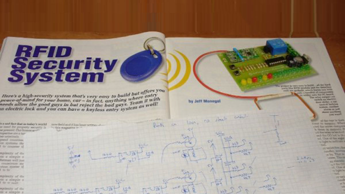
The purpose of this project is to prototype a basic RFID access system. Although it is not that complicated, this article is my response to a kit reviewed in the Australian “Silicon Chip” (November 2010) electronics magazine. Their article describes the kit in detail – operation, schematic, use and installation. However the code for the microcontroller (PIC16F628A) is not published due to the kit manufacturer holding copyright over the design. This is a shame, as many organisations have been quite successful selling open-source kits. So instead of moaning about it, I have created my own design that matches the operation of the original, instead using the ATmega328 MCU with Arduino bootloader. Consider this a basic framework that you can modify for your own access system, or the start of something more involved.
There are pros and cons with the original vs. my version. The biggest pro is that you can buy the whole kit for around Au$40 including a nice PCB, solder it together, and it works. However if you want to do it yourself, you can modify it to no end, and have some fun learning and experimenting along the way. So let’s go!
The feature requirements are few. The system must be able to learn and remember up to eight RFID access tags/cards, etc – which must be able to be altered by a non-technical user. Upon reading a card, the system will activate a relay for a period of time (say 1 second) to allow operation of a door strike or electric lock. Finally, the RFID tag serial numbers are to be stored in an EEPROM in case of a power outage. When a tag is read, a matching LED (1~8) will show which tag was read. There are also two LEDs, called “Go” and “Stop” which show the activation status. The original kit has some more LEDs, which I have made superfluous by blinking existing LEDs.
This is a simple thing to make, and the transition from a solderless breadboard to strip board will be easy for those who decide to make a permanent example. But for now, you can follow with the prototype. First is the parts list:
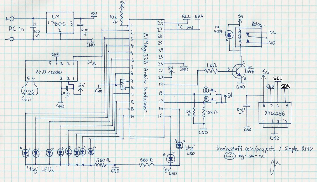
When selecting a relay, make sure it can handle the required load current and voltage – and that the coil current is less than 100mA.
[box color=”#985D00″ bg=”#FFF8CB” font=”verdana” fontsize=”14 ” radius=”20 ” border=”#985D12″ float=”right” head=”Major Components in Project” headbg=”#FFEB70″ headcolor=”#985D00″]
- Atmel ATmega328 with Arduino bootloader;
- 16 MHz resonator (X1 in schematic);
- ten LEDs of your choice;
- two normally-open push buttons;
- two 560 ohm resistors (all resistors 1/4 watt);
- one 1k ohm resistor;
- three 10k ohm resistors;
- one BC548 transistor;
- three 0.01 uF monolithic capacitors;
- one 100 uF electrolytic capacitor;
- one 1N4004 diode;
- Microchip 24LC256 EEPROM;
- 125 kHZ RFID module;
- 125 kHz RFID tags/cards;
- connecting wire;
- large solderless breadboard;
- LM7805 power regulator;
- relay of your choice with 5V coil (example).
[/box]
For more detail: Simple RFID access system using Arduino