Have you ever wanted to make a project that involved contact-less sensing? For example: to detect a door closing, to count the number of revolutions of a wheel, or make a speedometer? Then this Arduino Hall Effect sensor tutorial is for you!
This project uses a Hall Effect sensor to detect the presence of a magnet. Whenever a magnet moves past this sensor, it can detect it. This sensor can be used to do a lot of different things. For instance, if we need to detect a door closing; then we simply have to attach a magnet to the door and a hall sensor to the frame of the door. Whenever the door closes, the magnet is placed near the hall effect sensor and we are able to detect that the door has been closed.
Similarly, this same principle can be used to make a speedometer for a bike or any other vehicle. If a magnet is attached to the wheel and a Hall Effect sensor is placed somewhere in the frame of the bike, the time taken for the wheel to complete one revolution can be measured, and with a bit more math, we can detect the bike’s movement speed!
Required Materials
Hardware:
- Arduino or an Arduino clone board (freeduino), or make your own custom Arduino board with this tutorial.
- Hall effect sensor 44E or US5881 or US1881.
- A small magnet.
- 10K resistor.
- 9V Battery and connector.
- Connecting wires and breadboard.
Software:
How Does it Work?
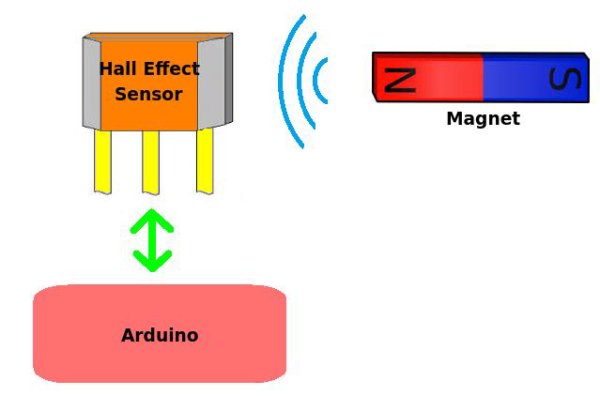
The Hall Effect sensor works on the principle of the Hall Effect, which states that whenever a magnetic field is applied in a direction perpendicular to the flow of electric current in a conductor, a potential difference is induced. This voltage can be used to detect whether the sensor is in the proximity of a magnet or not. The Arduino can detect this voltage change through its interrupt pin and determine whether the magnet is near the sensor or not. The basic working of the Arduino Hall Effect sensor is shown in the picture below.
There are many types of Hall Effect sensors, and certain types are better for certain applications. For applications where the speed of detection is not crucial, ordinary Hall Effect sensors like 44E can be used. However, for applications that involve high-speed detection, like in the case of speedometers, high-frequency Hall Effect sensors like US5881 or US1881 should be used. There are two main types of Hall Effect sensors:
- Latching Hall Effect sensors.
- Non-latching Hall Effect sensors.
The US1881 is a latching Hall Effect sensor. The sensor gives out an output HIGH (5V) voltage whenever the north pole of a magnet is brought close to it. Even when the magnet is removed, the sensor still outputs a HIGH voltage and does not go LOW (0V) until the south pole of the magnet is brought close to it. These sensors that latch on to a particular state are called latched Hall Effect sensors.
The US5881 is a non-latching Hall Effect sensor. The sensor gives an output HIGH voltage whenever the north pole of a magnet is brought close to it, and switches LOW whenever the magnet is removed. I personally prefer non-latching Hall Effect sensors like the US5881 for my projects.
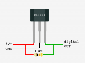
Hall effect sensors have three pins: VCC(5V), GND, and Vout(Signal). The pinout of a Hall Effect sensor is as shown below:
Making the Connections for the Arduino Hall Effect Sensor
Interfacing the Hall Effect sensor with Arduino is really simple. The VCC of the sensor is connected to Arduino’s 5V power pin. The GND of the sensor is connected to the GND pin on the Arduino. The Vout or Signal pin of the Hall Effect sensor is connected to the Arduino’s interrupt pin (digital pin 2). Furthermore, a 10K resistor is connected between the VCC and Vout pins of the Hall Effect sensor. This is done to pull the output of the Hall Effect sensor to 5V. The connections are done as shown below (the side with the printed number is facing towards you in the diagram):
Read More: A Simple Guide to Using a Hall Effect Sensor With Arduino