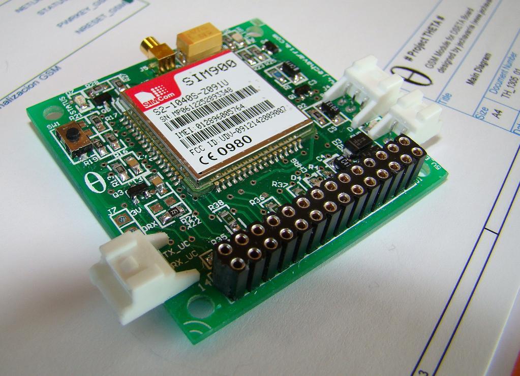
After some months out, I come back with my last board, the SIM900 Breakout Board. It’s a board based on the popular SIM900 GSM modem, and I design to work with the DSETA board I develop previously. Also, the board can be used without this board, I try to design it in the way that can be used with any microcontroller. From here, I want thanks to Ioannis Kedros from Embedded Day his support in the design of the battery charger, and to Sonia Muñoz, FAE from EBV, a great professional and a better friend, she always helps me when I need. So, let’s go to see what’s inside the board!
- The Hardware
In this post, I only cover the hardware of the board. In an upcoming entry, I’ll develop a full application with this board and I cover the software aspects of the design.
This board is designed to use with a microcontroller-based board. It can be powered from a Li-Ion battery, so includes all the necessary electronic to charge and monitoring the battery. The schematics of the board can be download here. As usually, the schematic is divided in functional blocks, and here’s a brief description of each:
Main Diagram: All the blocks of the system are in this page, including the the relationship between all the signals. Note that with R35-R38, you can isolate the DTR, RI, NETLIGHT and INFO signals from the IO connectors, if you don’t populate.
IO Connectors: This are the connection of the board with the rest of the world. It’s design to fit with the DSETA board, but you can use any other board or microcontroller to interface with it. The two connectors has 14 pins and has an standard 100 mils step. Here are the description of each pin of each connector:
Power Supply and Battery Charger: This board can be powered from three different sources:
- Power supply from external +5V (+5V_EXT) using J3 connector.
- Power supply form the IO connectors (+5V_USB), using pins #2 from J1 or J2 connectors.
- Battery supply, using J4 connector.
To allow two external +5V power supplies, I use schottky rectifier diodes from Vishay (SSA33L) to parallelize it. I use this voltage to charge the battery, through the U1. I use the Microchip MCP73832T-2ACI/OT battery charger. This device is a highly advanced linear charge management controller for Li-Ion and Li-Polymer batteries. As the battery has enough current to power the system, I fix the charge current at 100 mA, with a R4 value of 10K. The battery I use to power the system is the LP653450, a 3,7V / 1100mAh Li-Ion battery pack. The standard charging voltage for this battery is 4.2V, so the battery charger model must be fit with this requirement. From this stage, two signals goes to the IO connectors: CHARGE_STATUS, a digital signal that indicates if the battery is charging (also, led D4 indicates the status visually), and BATT_VOLTAGE, an analog signal to measure the level of the battery. The second part of the schematic corresponds to the LDO regulator. This circuit used the input voltage to obtain the +3.0V necessary for the digital part. So, the microcontroller or board you use with this module must be fit to this voltage. The regulator is the TC1173-3.0VOA from Microchip, that has a maximum dropout of 480mV. This regulator can give an output current of up 300mA, enough to power a board with a microcontroller. This output power supply is available in the IO connectors. And finally, the external +5V_EXT power supply is monitored with three independent circuits. Why? This is for a future application……stay tuned!
For more detail: SIM900 Breakout Board