Security system sensors such as motion detectors, reed switches, pressure mats, glass-break detectors, infra-red beams, and conductive film can be very handy for all sorts of things including home automation systems, interactive art installations – and sometimes even security systems! Almost all security system sensors provide a simple switched output that changes state based on whether the sensor has been tripped or not, which means that when connected up in a circuit they behave just like a switch that is activated automatically. That makes them extremely easy to connect to an Arduino to read their status.
However, things are not quite as simple as they may first appear.
Most security sensors provide a “normally-closed” output: that is, when they have not been tripped their output is a closed circuit, and when it has been tripped it goes open-circuit. This is the exact opposite behaviour of something like a simple push-button switch, which is normally open-circuit and then goes closed-circuit when you press it.

The reasoning behind closed-circuit outputs is that it allows an alarm panel to verify the integrity of the connection to the sensor. If an intruder cuts the wire going to a motion detector the central alarm panel will see that as the same thing as the detector being triggered, and will sound the alarm even though the detector itself has been totally removed from the circuit and can’t send back a signal to the panel.
That inverted logic is easily handled in software. If you want to use a security sensor for a non-security application such as triggering a kinetic sculpture when people walk up to it then you can treat a sensor as a simple switch and connect it to a digital input. Just remember that it will behave in the opposite way to a normal switch and you’ll be all set.
However, any professional alarm installer will tell you that such a simple approach is totally inadequate for sensors that are security-critical. Having a sensor that will trigger the alarm if the wire is cut is a good start, but it doesn’t go nearly far enough. What happens if an intruder climbs in through the roof, finds your motion detector wires inside the ceiling, strips back the insulation, and short-circuits them? It doesn’t matter what the sensor does then because the alarm panel will think the sensor circuit is good. The intruder can walk around inside your house with the alarm fully activated and it won’t even notice. Or what happens if someone gets underneath a motion detector without triggering it, such as by coming in through a doorway underneath it, and then removes its cover to mess with it? Or even more insidiously, what if someone was in your premises when the security system was disarmed (such as a customer in a store during regular opening hours) and took the opportunity to take the cover off a motion detector and bypass it so they could return later when the store is closed and the security system has been armed?
To guard against those sorts of attacks a security system needs to detect far more than a simple open or closed circuit. It needs to be able to detect if the wire to a sensor has been cut, or a wire short-circuited, or the sensor has been tripped. It also needs to detect if the sensor is being tampered with, even when the alarm system itself is in a “disarmed” state. Well-designed security systems treat all parts of the system as untrusted and can detect tampering in nearly any cable or sensor at any time, whether it is currently armed or disarmed.
In this project we’ll use the flexibility of the Arduino’s analog inputs to build sensor circuits that are as fully-featured as any professional system and will allow you to detect any of those possible failure, tamper, or trigger conditions automatically. You can then use your Arduino as a security system controller, or as part of a home automation system to turn lights on and off as you enter and leave rooms, or to control an art installation based on viewer activity.
[box color=”#985D00″ bg=”#FFF8CB” font=”verdana” fontsize=”14 ” radius=”20 ” border=”#985D12″ float=”right” head=”Major Components in Project” headbg=”#FFEB70″ headcolor=”#985D00″]
| Qty | Description |
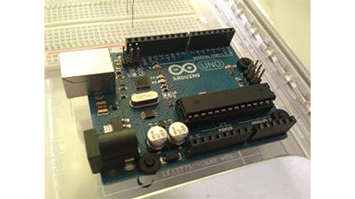
| 1 | Arduino Duemilanove, Arduino Pro, Seeeduino, or equivalent |
| 1 | Prototyping shield |
| 1 | 2-connection PCB-mount screw terminals (for 12V power) |
| 8 | 2-connection PCB-mount screw terminals (2 per channel, total 4 channels) |
| 1 | Green or blue LED |
| 1 | 1K5 resistor 1%: brown-green-black-brown-brown 5%: brown-green-red-gold |
| 4 | Red LEDs (1 per channel) |
| 4 | 680R resistors (1 per channel) 1%: blue-gray-black-brown-brown 5%: blue-gray-brown-gold |
| 4 | 1K resistors (1 per channel) 1%: brown-black-black-brown-brown 5%: brown-black-red-gold |
| 12 | 4K7 resistors (3 per channel) 1%: yellow-violet-black-brown-brown 5%: yellow-violet-red-gold |
| 4 | Passive infra-red (PIR) motion detectors with a simple switched output, not a “smart” PIR (1 per channel) |
| 1 | 12V power supply rated to at least 500mA |
| 20cm | Hook-up wire or ribbon cable |
| 4-core security cable long enough to connect to sensors |
[/box]
For more detail: Security / Automation Sensors using Arduino