What is this ?
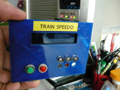
This project is a “real size” speedometer for miniature trains, cars and anything you wish to measure.
It can calculate the speed of the object between 2 measuring points along the track (or road) by counting milliseconds between passages at the start and end gates. If you enter the distance between those gates (in dm) and the used scale (ex. H0 = 1:87) in to the Arduino, it will calculate the actual “real” speed of the object if it were on a 1:1 scale in the real world. This is a useful tool for measuring and calibrating the speed of your model trains on the layout, in order to be able to set and control their speed in the PC or central station for a realistic run on the tracks.How does it work ?
2 detectors are set up along the track, at a known distance (in dm) from each other. When a train runs by one of the detectors, the timer is started, the switch is auto-disabled (to eliminate double counts or other forms of interference) and only when the object passes by the other detector, will the timer be stopped and will the module calculate the speed based on time , distance and scale factors.
Due to the auto-disable fuction of the detectors, the system can calculate either LTR or RTL (left to right or right to left) moving objects with the same accuracy.The commands :
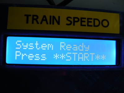
— START button : use this one to trigger the circuit and put it in stand-by so it will start measuring when an boject enters the test track section.
— ZERO button : to clear the display or to interrupt an ongoing measurement (bypass)
— MENU button : enters the 3 menu levels
* first push : enter the menu and go to the input screen for track length
* 2nd push : record the current setting and go to screen for scale input
* 3rd push : record the scale factor and go to the confirm / exit screen
* 4th push : confirm and store the new values or return to old ones and then go to main mode. (exit menu)
— UP / DOWN buttons : used to increment / decrement or change the values in the menu screen.
— HARD RESET button (optional) : for a full reset of the device (however, scale and length are stored in EEPROM and will be remembered)Detection ?
Detection is done using two IR LED / Transistor combinations, which create a “light vault” at each end of the measuring track/road.
The swithcing is “to ground” so when an object breaks the beam, the counter will start.
instead of IR vaults, you can also use conventional switches (contact switches), reed switches (magnetic), manual switches (like a stopwatch works) or any kind of detection that can swith a contact to ground.Release notes :
*1* due to limitations in EEPROM writeable values (0-254) the length of measurement is limited to 254 decimeters, meaning 25,5 M (approx 70 ft) which should cover most purposes. Bear in mind that the speed calculations are done in cm/s but the length of the test track is in dm (decimeters) when you enter it in the menu. All internal conversions are done by the Arduino module.
*2* for wiring and component saving reasons, ALL pull up resistors (internal ones) must be enabled on the input channels.
This project is a “real size” speedometer for miniature trains, cars and anything you wish to measure.
It can calculate the speed of the object between 2 measuring points along the track (or road) by counting milliseconds between passages at the start and end gates. If you enter the distance between those gates (in dm) and the used scale (ex. H0 = 1:87) in to the Arduino, it will calculate the actual “real” speed of the object if it were on a 1:1 scale in the real world. This is a useful tool for measuring and calibrating the speed of your model trains on the layout, in order to be able to set and control their speed in the PC or central station for a realistic run on the tracks.How does it work ?
2 detectors are set up along the track, at a known distance (in dm) from each other. When a train runs by one of the detectors, the timer is started, the switch is auto-disabled (to eliminate double counts or other forms of interference) and only when the object passes by the other detector, will the timer be stopped and will the module calculate the speed based on time , distance and scale factors.
Due to the auto-disable fuction of the detectors, the system can calculate either LTR or RTL (left to right or right to left) moving objects with the same accuracy.The commands :
— START button : use this one to trigger the circuit and put it in stand-by so it will start measuring when an boject enters the test track section.
— ZERO button : to clear the display or to interrupt an ongoing measurement (bypass)
— MENU button : enters the 3 menu levels
* first push : enter the menu and go to the input screen for track length
* 2nd push : record the current setting and go to screen for scale input
* 3rd push : record the scale factor and go to the confirm / exit screen
* 4th push : confirm and store the new values or return to old ones and then go to main mode. (exit menu)
— UP / DOWN buttons : used to increment / decrement or change the values in the menu screen.
— HARD RESET button (optional) : for a full reset of the device (however, scale and length are stored in EEPROM and will be remembered)Detection ?
Detection is done using two IR LED / Transistor combinations, which create a “light vault” at each end of the measuring track/road.
The swithcing is “to ground” so when an object breaks the beam, the counter will start.
instead of IR vaults, you can also use conventional switches (contact switches), reed switches (magnetic), manual switches (like a stopwatch works) or any kind of detection that can swith a contact to ground.Release notes :
*1* due to limitations in EEPROM writeable values (0-254) the length of measurement is limited to 254 decimeters, meaning 25,5 M (approx 70 ft) which should cover most purposes. Bear in mind that the speed calculations are done in cm/s but the length of the test track is in dm (decimeters) when you enter it in the menu. All internal conversions are done by the Arduino module.
*2* for wiring and component saving reasons, ALL pull up resistors (internal ones) must be enabled on the input channels.
The Schematic Diagram
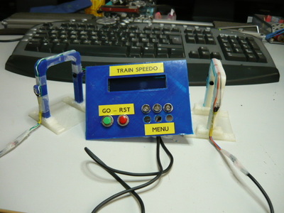
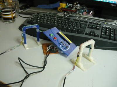
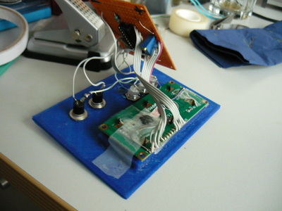
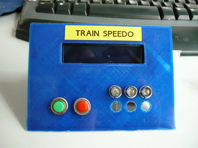
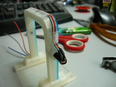
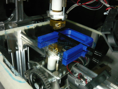
The Physical Build pictures
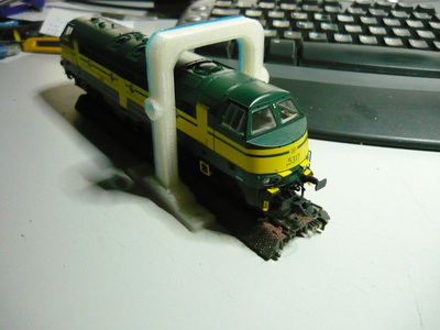
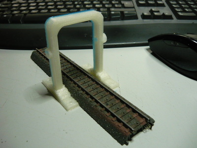
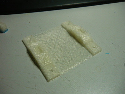
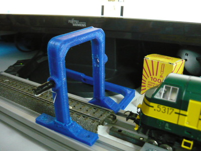
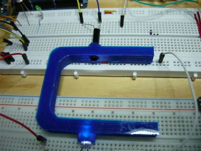
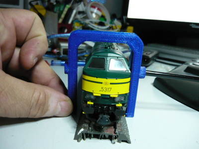
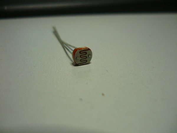
Note up front : during initial breadboard testing it turned out that instead of using IR equipment, which has a very limited detection range, a simple bright white LED with a 1K resistor as light source, pointed at a 20 ct LDR worked perfectly for switching the timer on/off. The distance between LED and LDR can be over 43 inch (7,5 cm) and it still works ok. The LDR just needs to be encapsulated in a 1 inch piece of black drinking straw or another piece of “tubing” to shield it from ambient light. You will see this “receiver” end on a piece of breadboard below. It will act as detector, and to make it “mobile” and stable, a 3D printed “detector portal” will be used. Of course, you can do the same with IR LEDs and IR fototransistors. The LDR simply switches the Arduino inputs to GND when it captures the bright light.
Speed conversion formulas.
We measure the distance between detectors in dm (decimeters) .
We measure the time in mS (milliseconds)
We measure the scale in units (ex. 87 = scale H0 = 1:87, 160 = Scale N = 1:160)
After some calculations (1000 mS in a second — 1 m/s = 3.6 km/h — 100 mm in a dm ) here is the formula :
Speed (km/h) = 360 * Distance (dm) * Scale (units) / Time (ms)
So a train covering 6 dm in 3838 mS (see movie) at scale H0 (87) would be going 48 km/h in reality.
The Arduino code and TinyCad design file
![]()
| scalespeedo.dsn |
![]()
| initeeprom_speedo.ino |
![]()
| _0_trainspeed.ino |