Web-enable your interactive sensors over desktop, smartphone and tablet devices.
This tutorial describes in detail how to use the free SensorMonkey service to remotely control a pan and tilt webcam attached to an Arduino using nothing more than a simple webpage. The webpage can be viewed on any desktop, smartphone or tablet device with a compatible web-browser. I use the jQuery UI library to provide interactive pan and tilt controllers and Justin.tv to provide the live streaming audio/video output captured by the webcam. No server-side coding or Ethernet shield is required.
In a previous tutorial, I described in detail how to use SensorMonkey to push real-time sensor data from an Arduino to a webpage for visualization using Processing.js (Disclosure: I co-founded the company developing SensorMonkey). I used an accelerometer to sample motion data and published it live over the Internet for people to view its output. The resulting webpage could be embedded into an external website to act as a real-time streaming widget. Communication was uni-directional; the data flowed from the Arduino through SensorMonkey and into the webpage. This tutorial demonstrates the opposite; namely, the data flows from the webpage through SensorMonkey and into the Arduino.
Important! Although not strictly necessary, it is recommended that you have read the previous tutorial in this series (at the very least, you should be familiar with the basic workflow used to connect an Arduino to SensorMonkey).
Step 1: Gathering Materials
The following combination of hardware and software is required to complete this tutorial:
Hardware:
- Arduino (I use an Uno but older boards such as a Duemilanove will work fine)
- USB cable to connect Arduino to host computer
- 2 x servo motors – one for pan and one for tilt (I use Hitec HS-422 Deluxe servos)
- Mounting brackets to construct pan and tilt assembly using servos (I use a Lynx B-Pan/Tilt kit)
- A base of some kind to stabilize your pan and tilt assembly (I use a cheap plastic mini-vice!)
- Webcam (I use a Microsoft LifeCam VX-3000 but any will do as long as it’s compatible with your OS)
- External power supply to provide current to servos (I use rechargeable Ni-MH 9V batteries)
- 9V to barrel jack adapter to connect external power supply to Arduino
- Assorted wires to connect pan and tilt assembly to Arduino
- Breadboard
Software:
- Arduino development environment (http://www.arduino.cc)
- Free account on SensorMonkey.com (login with your existing Facebook account)
- Free account on Justin.tv (for live audio/video streaming)
- Bloom (for Windows users) or SensorMonkeySerialNet (for non-Windows users)
- jQuery UI
You can buy the servos and mounting brackets separately or as a single kit.
The 9V batteries don’t last long, so if you want to setup your webcam for an extended period of time you’ll need to hook it up to a persistent external power supply such as a wall-mounted DC adapter or a high-power density LiPo battery.
Alternatively, you can power one of the 2 servos using another Arduino connected to a different USB port.
Step 2: Mount Webcam, Connect Arduino and Upload Sketch
First, I build the pan and tilt assembly by attaching the servos to the mounting brackets as described here (if you’re using different components, please follow the relevant assembly guide(s) for your particular servos and mounting brackets instead).
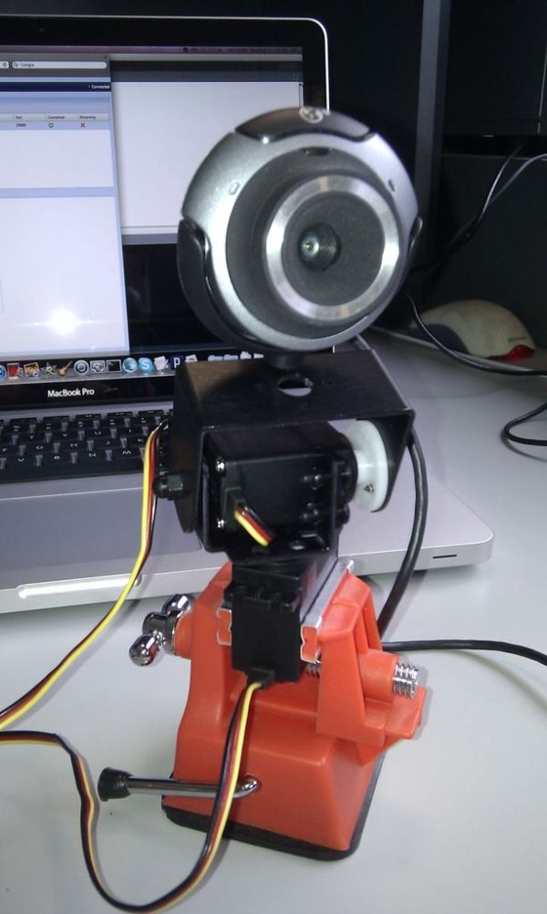
Next, I attach the webcam to the top of the tilt servo’s mounting bracket. In my case, I simply had to remove (unscrew) the universal attachment base from the bottom of the webcam and screw the device into one of the holes in the mounting bracket. Depending on your webcam, you may need to attach it by some other means (you can always use sticky tape if all else fails!).
To stabilize the whole assembly, I place it into the plastic mini-vice and fix the vice to a flat surface (i.e. the top of my desk). Again, depending on your components, you may have other requirements. As long as the webcam can pan and tilt without falling over that’s all that matters.
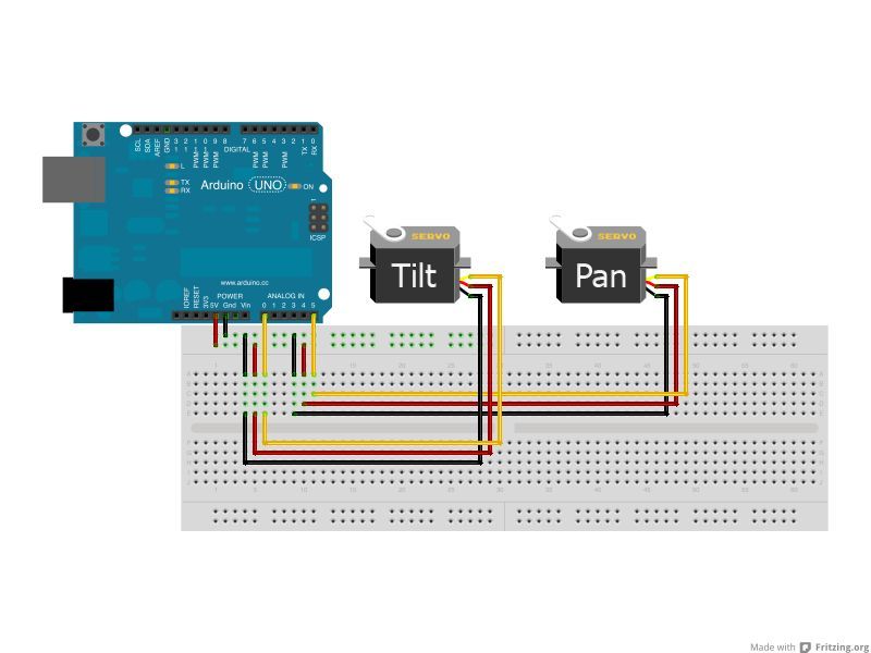
From here, I wire the servos to the Arduino as shown in the pictures and the circuit diagram (made using Fritzing). The tilt servo is connected to analog pin 0, while the pan servo is connected to analog pin 5. The Arduino is connected to the host computer using the USB cable and powered using the external power supply through the built-in barrel jack adapter.
Finally, to control the servos, I upload the following sketch to the Arduino’s microcontroller using the development environment:
#include <Servo.h>
Servo pan, tilt;
void setup() {
pan.attach( A5 );
tilt.attach( A0 );
Serial.begin( 9600 ); // Open the serial port.
}
void loop() {
if( Serial.available() ) {
byte b = Serial.read();
// Map high 4 bits of incoming byte to pan rotation in degrees.
pan.write( map( b >> 4, 0, 15, 0, 180 ) );
delay( 15 );
// Map low 4 bits of incoming byte to tilt rotation in degrees.
tilt.write( map( b & 0x0F, 0, 15, 0, 180 ) );
delay( 15 );
}
}
The sketch is very basic. It opens the serial port and reads bytes one at a time. Each byte is assumed to contain a pan and tilt rotation pair; the high 4 bits are the pan rotation (0 to 15 inclusive) and the low 4 bits are the tilt rotation (0 to 15 inclusive). This gives 16 different levels (i.e. 24) to choose from with respect to each dimension of motion and makes it easy to encode the webcam’s position using hexadecimal character pairs. Each servo has a range of 0 to 180 degrees. So, for example, a hexadecimal character pair of 7A means 7/15 x 180 (84 degrees) on the pan axis and 10/15 x 180 (120 degrees) on the tilt axis. A hexadecimal character pair of 00 encodes a 0 degree rotation on both pan and tilt axes, while FF encodes a full 180 degree rotation on both pan and tilt axes. The mapping for each character is shown below:
0 : 0 degrees
1 : 12 degrees
2 : 24 degrees
3 : 36 degrees
4 : 48 degrees
5 : 60 degrees
6 : 72 degrees
7 : 84 degrees
8 : 96 degrees
9 : 108 degrees
A : 120 degrees
B : 132 degrees
C : 144 degrees
D : 156 degrees
E : 168 degrees
F : 180 degrees
If I needed fine-grained control of the servos’ motion, I could encode the pan and tilt rotations as separate bytes. In this case, however, using a single byte only is an efficient means of encoding the co-ordinate system for controlling the two servos and provides adequate motion range for a simple webcam.
[box color=”#985D00″ bg=”#FFF8CB” font=”verdana” fontsize=”14 ” radius=”20 ” border=”#985D12″ float=”right” head=”Major Components in Project” headbg=”#FFEB70″ headcolor=”#985D00″]
- Arduino (I use an Uno but older boards such as a Duemilanove will work fine)
- USB cable to connect Arduino to host computer
- 2 x servo motors – one for pan and one for tilt (I use Hitec HS-422 Deluxe servos)
- Mounting brackets to construct pan and tilt assembly using servos (I use a Lynx B-Pan/Tilt kit)
- A base of some kind to stabilize your pan and tilt assembly (I use a cheap plastic mini-vice!)
- Webcam (I use a Microsoft LifeCam VX-3000 but any will do as long as it’s compatible with your OS)
- External power supply to provide current to servos (I use rechargeable Ni-MH 9V batteries)
- 9V to barrel jack adapter to connect external power supply to Arduino
- Assorted wires to connect pan and tilt assembly to Arduino
- Breadboard
[/box]
For more detail: Remote controlled webcam using Arduino