After I built R/C Lego Car, that used hacked motors and motor housings from the toy Car and toy R/C cars. I realized most of the parts from that toy R/C car that I took the motor out of became wasted.
This way was not very practical or not so “green” at all.
 So I decided to design a 3D printed motor housing (See details in Step1) that is generic to all of my Lego car designs (details in Step 1).
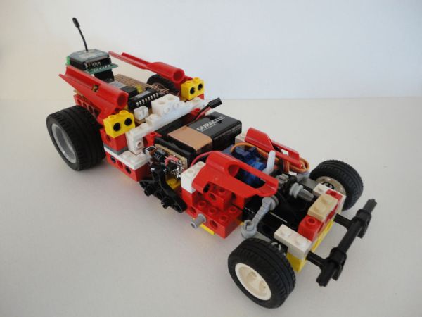
This instructable, R/C Lego Car Redux, shows you how to use the 3D printed motor housing with my very first built R/C Lego Car.
Most of the parts from my original R/C Lego Car were still in used in this version. There were also some new Lego parts added, but only a few.
Eventhough this instructable is a “Redux” of the R/C Lego Car, I am going to show you how to build this car step by step from scratch, just like we tear the model apart and rebuild it again.
One good thing, neither the programming the Arduino, nor the UI to control the car in Processing needed to be changed.
Note: See more photos of “Redux” version of R/C Lego Car and video in Step 12.
Enjoy!
Disclaimer:
LEGO®, TECHNIC, are property of The LEGO Group of Companies (http://www.lego.com), which does not sponsor, own, authorize or endorse this creation.
Step 1: 3D Printed Motor Housing
Why 3D Printed Motor Housing?
I was not very happy and was tired of using hacked motor and motor housing from toy car or toy R/C car, because each time I want to build a different design Lego Cars. Most of the time the new design Lego car that I plan to make was not able to use the previous hacked motor and motor housing.
Now that I created my own 3D printed motor housing. My motor housing for custom LEGO® car can be used over and over, and I do not have to buy toy R/C car to hack for motor housing from it and mod it to fit with my new design Lego car anymore.
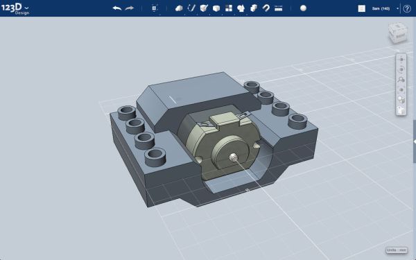
This 3D motor housing was designed to have studs (4×6 studs) that compatibles with LEGO® modular system.
printed motor housing fits most of DC gear motors (130-Size), standard toy DC motors, with the approximate size of 15x20x25mm (height x width x length) with 2mm shaft diameter.
Photo 1 Screen grabbed from the 123D Design of the finished 3D model of motor housing.
Photo 2, 3 The 3D printed motor housing used in this project was first created in 123D Beta 9, and then migrated to 123D Design, both have the similar functionalities. The 3D printed motor housing was first printed from The Free 3D Printing offer from instructables.com (now closed).
Photo 4, 5, 6 Show the installation of the motor housing on my Wireless Lego Race Car.
Here are the steps I made to create 3D printable motor housing in 123D Design,
Photo 7 Before I migrated from 123D Beta 9 to 123D Design I tried out the 123D Design app. by created 130-Size motor in the 123D Design first.
Photo 8 Then I created 1×4 LEGO Brick.
Photo 9 And then added Primitives, and used Combine tools to form the housing.
Photo 10 And 3D Printing ready model.
Photo 11 I hided the motor model and ready to send to fabricator.
Attached is the STL file, you also can view the model and download the file from Shapeways here.
Step 2: Parts & Tools
[box color=”#985D00″ bg=”#FFF8CB” font=”verdana” fontsize=”14 ” radius=”20 ” border=”#985D12″ float=”right” head=”Major Components in Project” headbg=”#FFEB70″ headcolor=”#985D00″]
Lego Bricks
Following is the list of Lego parts that I used for building this car.
Most of the parts are from my previous built R/C Lego Car. Some addition parts were from ebay.
If you want to do this R/C Lego Car with the different color, please feel free to do so.
Note: The number in the bracket is the Lego’s Design ID.
2 no. – 1×12 Technic brick (#3895)
6 nos. – 1×8 Technic Brick (#3702)
7 nos. – 1×6 Technic Brick (#3894)
15 nos. – 1×4 Technic Brick (#3701)
10 nos. – 1×2 Technic Brick (#32000)
4 nos. – 1×2 Technic Brick with hole (#3700)
1 no. – 1×2 Brick with Horizontal Snap (#2458)
4 nos. – 2×8 Technic Plates (#3738)
1 no. – 2×6 Technic Plate (#32001)
4 nos. – 2×4 Technic Plate (#3709)
2 nos. – 2×3 Standard Plate (#3021)
2 nos. – 2×2 Standard Plate (#3022)
3 nos. – 1×8 Plate (#3460)
2 nos. – 1×6 Plate (#3666)
11 nos. – 1×4 Plate (#3710)
5 nos. – 1×2 Plate (#3023)
1 no. – 1×4 Flat Tile (#2431)
1 no. – Bush for Cross Axle (#6590)
2 nos. – Bush 1/2 Toothed Type II (#4265b)
1 no. – Bush for Cross Axle (#6590)
1 no. – 1/2 Bush (#32123)
3 nos. – Connector Peg/Cross Axle (#6562)
14 nos. – Connector Peg (#3673)
8 nos. – Connector Peg With Friction (#2780)
4 nos. – Connector Peg 3M (#32556)
1 no. – Cross Axle 12M (#3708)
1 no. – Cross Axle 6M (#3706)
1 no. – Cross Axle 3M (#4519)
2 nos. – Axle Joiner Perpendicular (#6536)
Steering Kit
1 no. – 1x 8 Steering Rack Bracket Plate (#4262)
1 no. – Steering Gear Holder (#2790)
1 no. – Steering Rack Top (#2792)
1 no. – Steering Rack (#2791)
2 nos. – Steering Arm Drop Link (#4261)
3 no. – 8-Tooth Gear (#3647)
24-Tooth Crown Gear Type III (#3650)
Servo horn glued to Axle 3L with Stud (#6587)
Wheels and Rims
Front
2 no. – Tire size 30.4 x 14 VR (#6578)
2 no. – Wheel size 30.4 x 14 VR (#2994)
Rear
2 no. – Tire size 43.2 x 22 ZR (#44309)
2 no. – Reinforced Rim with no pin holes 30.4mm D x 20 mm (#56145)
2 nos. – Lift Arm Triangles Thin (#2905)
2 nos. – 1x2x2 Corner Plate (#2420)
1 no. – Panel Fairing #5 (#32527) Red
1 no. – Panel Fairing #6 (#32528) Red
1 no. – Panel Fairing #7 (#32534) Red
1 no. – Panel Fairing #8 (#32535) Red
Servo
9g Micro Servo (T Pro SG90)
Motor
4.5V – 9V, 130-Size Motor
3D Printed Motor Housing
2mm Shaft Adapter for Lego Wheels (Pololu part #1001)
(or Modified Connector Peg/Cross Axle (#6562) to fit the shaft of DC toy motor.)
Arduino and Motors Driver
Arduino or Arduino compatible (I used DIY Arduino in this project.)
L293D (or SN754410) motors driver IC
XBee module
Xbee breakout board (I used XB-Buddy Basic Kit, Jameco’s Part no. 2163680)
PCB (approximately 2″x3″)
Hook up Wire
[/box]
Tools
Sugru
X-ACTO Knife
Sand paper
Files
Step 3: Steering System & Front Bumper
Following are the photos show how to assemble parts:
Photo 1 One 2×4 Technic Plate (#3709)
Photo 2,3 Two 1×8 Technic Bricks (#3702)
Photo 4,5 One 1×4 Flat Tile (#2431)
Photo 6,7 Steering Gear Holder (#2790) and Steering Rack Top (#2792)
Photo 8 Steering Rack (#2791)
Photo 9,10 Two Connector Peg/Cross Axles (#6562) and Two Steering Arm Drop Link (#4261)
Photo 12 8-Tooth Gear (#3647)
Photo 13 Servo horn glued to Axle 3L with Stud (#6587).
(See details of how to make the servo axle in Step 4 of R/C Lego Car )
Photo 14,15 One 1/2 Bush (#32123)
Photo 16,17,18 Connector Peg/Cross Axle (#6562) and Two Tire (Balloon) size 30.4 x 14 VR with rims (#2994)
Photo 19,20,21 One 1x 8 Steering Rack Bracket Plate (#4262) and 1×2 Brick with Horizontal Snap (#2458)
Photo 22,23 One 1×6 Technic Brick (#3894) and Two 1×2 Plates (#3023)
Photo 24,25 Two 1×2 Plates (#3023)
Photo 26 One 1×4 Technic Brick (#3701)
Photo 27,28 1×2 Plate (#3023)
Photo 29 Two 3M Connector Peg (#32556)
Photo 30,31,32 Cross Axle 6M (#3706) and Two Axle Joiner Perpendicular (#6536)
Step 4: Car Front Frame
Following are the photos show how to assemble parts:
Photo 1 One 1×12 Technic brick (#3895)
Photo 2,3 Connector Peg 3M (#32556), one grey, one black
Photo 4,5,6 One 1×6 Technic Brick (#3894) and Two Connector Peg with Friction (#3673)
Photo 7,8,9 Repeat of photos 1 to 6
Photo 10 Add parts to Steering System from Step 3
Photo 11 One 2×4 Technic Plate (#3709) and 2×8 Technic Plate (#3738)
Turn the finished part upside down. Attach both parts to the Steering system as shown.
Photo 12 Two 1×4 Technic Brick (#3701)
Photo 13 Two 1×2 Technic Bricks (#32000)
Photo 14,15 Two 1×2 Technic Bricks (#32000)
Photo 16,17,18 Modified Technic plate for Servo support.
For servo support pieces, see how to make them in Step 4 of R/C Lego Car:
Photo 19 Now, we have the front frame done.
Step 5: Battery Compartment
This step we’re continuing on to build the battery compartment.
Following are the photos show how to assemble parts:
Photo 1,2,3 Two 1×8 Technic Bricks (#3702) and Two Connector Peg with Friction (#3673)
Photo 4,5 Three 2×8 Technic Plates (#3738)
Photo 6 Two 2×3 Standard Plates (#3021)
Photo 7,8,9 Four Connector Pegs with Friction (#3673) and Two Lift Arm Triangles Thin (#2905)
Photo 10,11,12 Two 1×4 Plate (#3710) and two 1×4 Technic Brick (#3701)
Photo 13,14 Two 1x2x2 Corner Plate (#2420)
Photo 15,16,17 Two 1X2 Technic Brick with 2 holes Ø4,87 (#32000)
Step 6: Motor Housing
Following are the photos show how to assemble parts:
Photo 1 2mm Shaft Adapter for Lego Wheels
Photo 2 Install shaft adapter (Pololu #1001) or Modified Connector Peg/Cross Axle (#6562) to motor.
Photo 3.4 Insert the motor with shaft adapter to the 3D printed motor housing.
Photo 5,6 Fit the 8-Tooth Gear (#3647) to the shaft adapter.
Photo 7 Continue on from last step (Step 5)
Photo 8, 9 Install 2×6 Technic Plate (#32001)
Photo 10,11 Place the motor housing (that we just finish in this step) to the car frame.
Photo 12,13 Two 1×4 Technic Bricks (#3701)
Photo 14,15 Two 1×4 Technic Bricks (#3701)
Photo 16,17,18 Two 1×4 Technic Bricks (#3701) and Four Connector Pegs with Friction (#3673)
Step 7: Gear Box
New parts:
24-Tooth Crown Gear Type III (#3650)
Cross Axle 12M (#3708)
Following are the photos show how to assemble parts:
Photo 1,2 Cross Axle 12M (#3708) and Bush for Cross Axle (#6590)
Photo 3 24-Tooth Crown Gear Type III (#3650)
Photo 4, 5, 6 Two Bush 1/2 Toothed Type II (#4265b)
Photo 7,8 Two 1×6 Technic Bricks (#3894)
Photo 9, 10 Two tires (Balloon) size 43.2 x 22 ZR with rims (#56145)
Photo 9, 10 Two 1×6 Technic Bricks (#3894), Cross Axle 3M (#4519), 8-Tooth Gear (#3647), and Bush for Cross Axle (#6590)
Photo 11,12 1×6 Plates (#3666)
Photo 13,14 Connect the Gear Box to the finished part from previous Step
Step 8: Frame Construction (Cont.)
Following are the photos show how to assemble parts:
Photo 1 Finished parts from last Step.
Photo 2, 3, 4, 5 Four 1×4 Technic Brick (#3701) and Four Connector Peg With Friction (#2780)
Photo 6, 7, 8 1×6 Plate (#3666) and Two 1×8 Technic Bricks (#3702)
Photo 9, 10 Two 1×4 Plate (#3710) and two 2×4 Technic Plate (#3709)
Photo 11, 12, 13 Four 1×4 Plate (#3710)
Photo 14, 15 Two 2×2 Standard Plates (#3022)
Photo 16, 17 Four 1×2 Technic Brick with Ø4.9 hole (#3700)
Photo 18, 19 Two 1×8 Plate (#3460)
Photo 20, 21 Two 1×4 Plate (#3710)
Photo 22, 23 Installed the DIY Arduino and Motors Driver PCB that we are already built from the previous version.
Step 9: Additional Decorative Panels
New parts:
1 no. – Panel Fairing #5 (#32527) Red
1 no. – Panel Fairing #6 (#32528) Red
1 no. – Panel Fairing #7 (#32534) Red
1 no. – Panel Fairing #8 (#32535) Red
Following are the photos show how to assemble parts:
Photo 1, 2, 3, 4 Panel Fairing #7 (#32534), Panel Fairing #8 (#32535), four Connector Peg With Friction (#2780), and Two 1X2 Technic Brick with 2 holes Ø4,87 (#32000)
Photo 5, 6, 7, 8 1×2 Technic Brick (#32000), 1×4 Plate (#3710), and 1×8 Plate (#3460)
Photo 9, 10, 11 Panel Fairing #5 (#32527), and Panel Fairing #6 (#32528)
Photo 12, 13 The Battery Compartment could accommodates 4×1.5V AA type battery with holder, or 7.5V 500mAh rechargeable LiPo battery, or 9V battery.
For more detail: R/C LEGO® Car Redux