Previously, we presented a general overview of the Quark D2000 development board. Subsequently, we explored the use of the board’s GPIO and PWM.
In this project, we will explore using I2C with the D2000 board by interfacing an ambient light sensor and a COG (chip-on-glass) LCD.
Since our last report, a new version of the board’s software interface has been released (ISSM_2016.1.067) and some of the documentation has been updated. Be sure to get the resources linked below:
- Using GPIO and PWM on the Quark D2000 development board
- Main Quark D2000 documentation page (links to User Guides, Design Notes, schematic and more)
- Intel Quark Microcontrollers forum
- Intel System Studio forum
- Where to get the Quark D2000 Development Board
Basic I2C Programming
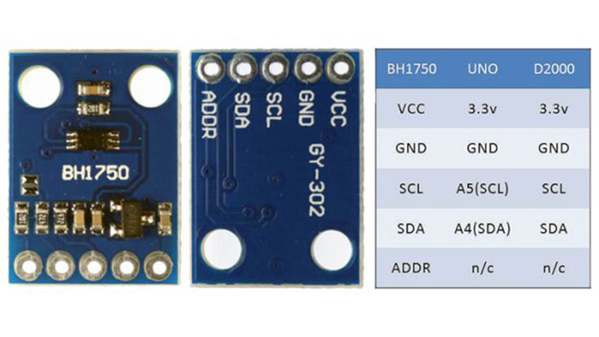
To illustrate the most basic use of the D2000 board’s I2C interface, we can compare the procedure to that used with the ubiquitous Arduino Uno. That is, we will interface a BH1750FVI ambient light sensor, using the module shown below, with each board.
This inexpensive module has been around for a while and is available from several sources (e.g., 1, 2). It’s chosen as an example because the programming to use the board is short and straightforward. Connecting the module is also straightforward (see right panel of the figure above) and it can be used with both 3.3V and 5V systems.
First, connect the board to the UNO and run the included program, BH1750.ino. You should see lux values scrolling on the serial monitor. Looking at the program listing, notice that we first #include wire.h and use the statement wire.begin() in setup(). Then, we call the function initBH1750(), also from setup(). Finally, we read the sensor values within the loop().
To initialize the sensor in initBH1750() we use the statements:
(1) Wire.beginTransmission(BH1750addr);
(2) Wire.write(BHmodedata);
and, then (3) Wire.endTransmission()
The statements; 1) set the address of transmission to the sensor using the variable BH1750addr, 2) cue writing the initialization code in the variable BHmodedata to the sensor, and, 3) actually write the data to the sensor.
In the loop() section, we read the sensor using the statements:
(1) Wire.requestFrom(BH1750addr, BYTES2READ);
(2) BHlxdata[0] = (byte)Wire.read(); BHlxdata[1] = (byte)Wire.read();
These statements; 1) send a request to the device to read two bytes of data (the lux value), and 2) read two bytes from the sensor and store them in variables. The program then converts the bytes read to a lux value and prints the value to the serial monitor.
BH1750.c is the analogous program for the D2000 board. After you connect the sensor module, you can compile and run this program by first creating a new project for the D2000 board (make sure you specify QMSI 1.1) in System Studio using an existing template (“Hello World” works fine). Rename it as desired and then copy and paste BH1750.c over the existing code (main.c) and you are ready to Build and Run the program. All of the included D2000 programs will work in this same manner.
To get a sense for how I2C can work on the D2000, we can compare the two programs.
First, instead of including wire.h, we will include qm_i2c.h. This header file and the associated .c file contain the source code for the I2C routines. It is a very good idea to become familiar with these two files if you want to use and understand I2C on the board. You will find them among your installation directories – \IntelSWTools\ISSM_2016.1.067\firmware\bsp\1.1\drivers and IntelSWTools\ISSM_2016.1.067\firmware\bsp\1.1\drivers\include
The function wireBegin() contains the necessary setup calls to use the I2C and the code is listed below.
/*  Enable I2C 0 */
	clk_periph_enable(CLK_PERIPH_CLK | CLK_PERIPH_I2C_M0_REGISTER);
	/* set IO pins for SDA and SCL */
	qm_pmux_select(QM_PIN_ID_6, QM_PMUX_FN_2);
	qm_pmux_select(QM_PIN_ID_7, QM_PMUX_FN_2);

/* Configure I2C */
	I2Ccfg.address_mode = QM_I2C_7_BIT;
	I2Ccfg.mode = QM_I2C_MASTER;
	I2Ccfg.speed = QM_I2C_SPEED_STD;

/* set the configuration through the structure and return if failure */
	if (qm_i2c_set_config(QM_I2C_0, &I2Ccfg)) {
		QM_PUTS("Error: I2C_0 config\n");
		return (errno);
	} else {
		return (0);
	}
First, we enable clocking for I2C. Next, we select the desired function for the I/O pins which will be used for the SDA and SCL I2C lines. In this regard, you can download a handy illustration of the identification of each of the board’s I/O pins and their multiplexed functions.
In the global variables section, we defined a structure with the line: qm_i2c_config_t I2Ccfg.
Our next step is to configure parameters of the I2C using this structure. Specifically, we set the addressing mode to 7-bit, the role to master, and the speed to standard. Finally, we set this configuration by calling the system function, qm_i2c_set_config() with our configuration structure as an argument.
The code lines above make use of definitions that appear in qm_i2c.h. For example; QM_I2C_SPEED_STD set the speed to 100 Kbps, whereas QM_I2C_SPEED_FAST sets the speed to 400 Kbps, and QM_I2C_SPEED_FAST_PLUS sets the speed to 1 Mbps.
Our function initBH1750() reads the sensor values. The integral component of the function is a call to the system function qm_i2c_master_write().
uint8_t BHmodedata[1] = {0x10}; /* BH1750 initialization code for 1 lux resolution */
	if (qm_i2c_master_write(QM_I2C_0, BH1750addr, BHmodedata,
			sizeof(BHmodedata), true, &I2Cstatus)) {
		return (errno); 	/* error code (errn) */
	}
Read More: Add a Light Sensor and an LCD