This is my Halloween costume for the year 2013. It’s been in the works for about a year and has taken quite a few man hours to create. The screen is 14 by 15 pixels, so, pretty low resolution but it can still do some fun things. It is physically flexible in all directions, although it cannot be folded without damage. It has a controller consisting of a single button and slide pot, connected to a pro mega via USB. To keep it alive for a long time it employs two monstrous 2200 mAh batteries wired in series to get the necessary voltage, and then a 5 Volt regulator to make it usable. All the electronics are place in pockets on the inside of the shirt so they can be removed and so the shirt can be washed.
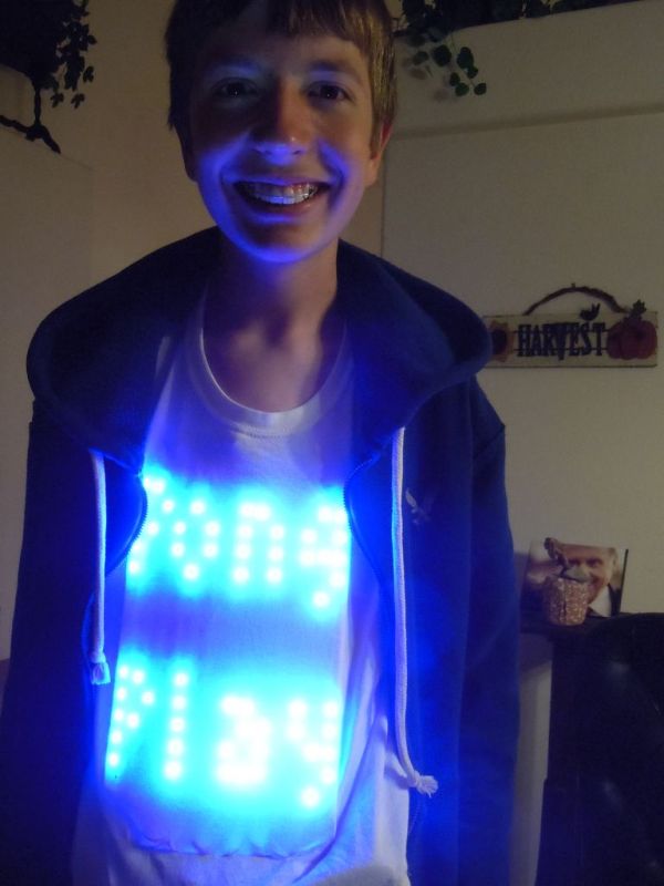
It plays a functional game of pong. It first graces one with the words “PONG PLAY” in lovely blue lettering using a modified version of the Tom Thumb font (can be found at http://robey.lag.net/2010/01/23/tiny-monospace-font.html). After five seconds the option can be given to press the button to move on, or to not press the button and leave a perfectly good experience behind. When one chooses to press the button, the game begins. A red paddle on the right is the computer paddle and the green paddle on the right is the player paddle, which is controlled by the slide pot to move up and down. The ball bounces around as each side tries to score a point. The player can hit the ball with the edge of their paddle to speed it up (a nice feature) while the computer cannot do this, and instead ends up being stuck with moving slightly slower than the ball. When a point is scored a pixel changes to white on the scoring sides paddle. It counts in binary from the bottom. where green or red is zero and white is 1. 21 is the score to win (or lose depending on who get’s 21 points) and so when the player paddle reads 10101, the “YOU WIN” text is displayed. Once again in modified Tom Thumb. The same happens but with “YOU LOSE” displayed instead. After a win or loss the game restarts to the point right after Pong Play. To restart entirely the restart button on the “Magic Box”, also known as the-box-with-all-the-electronics-except-the-screen, is pressed.
Step 1: Materials and Tools
[box color=”#985D00″ bg=”#FFF8CB” font=”verdana” fontsize=”14 ” radius=”20 ” border=”#985D12″ float=”right” head=”Major Components in Project” headbg=”#FFEB70″ headcolor=”#985D00″]
Things marked with a * are optional but recommend
And so in no particular order…
Materials:
4 Yards of Adafruit Neopixle 60 pixle per meter strip
1 T-shirt
*1 pair of Suspenders
1/2 yard of fabric will be more than enough (Non stretchy weave is preferred)
6 foot USB A male to USB B male cable
1 USB A female connector
3 2 pin JST female connectors
4 2 pin JST male wires
battery charger
2 6600 mAh batteries
1 Arcade style Button
1 arduino pro-mega
1 FTDI header
1 USB B female connector with breakout board
1 on/off switch (toggle)
1 reset switch (toggle or momentary)
1 slide potentiometer
*1 slide pot knob
1 high amp connector pair
*1 project case
1 5V 3+ amp voltage regulator
a small bit of plastic
some solder
some wire
some thread
*some hot glue
*some elastic
some time (Maybe a little bit more than “some”)
some perseverance (You will probably need quite a bit of this actualy)
some heat shrink tubing or electrical tape
some super glue
some iron on backing[/box]
Tools
*Helping Hands
Normal Hands (or someone with access to them)
Soldering Iron
*Hot Glue Gun
Dremel or Sandpaper
Chisel
Wire Strippers
Wire Cutters
Staple Gun
Screw Driver
Saw
Pins
Sewing Machine
Fabric Scisors
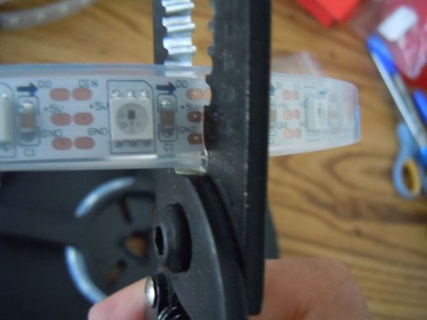
Step 2: Cut the LED Strip Into Smaller Strips
Use you’re preferred cutting utensil and cut the strip into 14 segments, each 15 pixels long.Cut only between the copper traces, labeled something like “DO” “DIN” “+5V” and “GND”. If it is already soldered over the copper their just cut right through. Try not to cut too much into the exposed copper but if you nick it a little that is just fine. Once all 14 of the strips have been cut, trim a little bit of the rubber off each end to get it out of the way for soldering the strips.
Step 3: Soldering the Screen Together
Take the wire and cut it into about 3.5 inch (9 cm) segments. In my case I have three different colors to make it easier to keep straight when soldering, but one color would work just fine. You will need about 40 of these little guys, but cut a couple more just in case.
Once You have finished cutting the wire, strip and tin the ends (If you have soldering experience you can skip to the next paragraph), meaning after you remove the little bit of plastic put some solder on the ends of each wire. Don’t heat the solder and try to move to to the wire, heat with you’re soldering iron from the bottom of the copper and put the solder on the top. Be patient and wait for the hot wire to melt the solder. It is tempting to tough the soldering iron to the solder to get it started (My impatience and I know exactly how you feel) but the solder won’t stick as well. Do the same for the exposed copper traces on each end of the strip sections. If it already has solder don’t worry about it. For the strip you may want to build up a little mound to make it easier later. When working with the strip, do it quickly, and try to not spend to much time applying heat to the strip. Only do what you need to do to melt the solder onto the trace.
Solder a wire on each trace to the end of the first strip (The first strip being the one with the wires and connector, solder it to the exposed end). If you look at the strip you will see little arrows on it going up to the end where you soldered the wire. Take another strip so that the arrows are pointing the opposite direction, and solder the wire coming from the GND trace to the GND trace of the other, the +5V to the +5V and so on. Repeat this making sure the arrows switch directions after every section so that if you were to follow them it would zig zag up and down, and that it could be stretched out to on long strip in the end.
Once all 14 strips have been soldered, lay them out and line then up so the LED’s form a grid. Then keep them together using a method that can be removed later without damage to the strip. I used scotch tape. It’s sticky enough to keep everything together but not so sticky as to leave a residue. I do not recommend anything to permanent, like staples or duct tape.
Once everything has been taped together solder a wire from the strip on the bottom +5V to the one immediately next to it. Repeat until the the entire bottom has the power taps going all the way across. This is so the screen doesn’t dim as the line of LEDs progress.
For more detail: Pong Playing Flexible Screen on a Shirt