1. Overview
The Wixel shield seamlessly enables a wireless link (with a typical range of ~50 feet) to replace your Arduino’s USB interface, which means you can use the standard Arduino computer software to:
- wirelessly program the Arduino (this feature is not available with the Arduino Leonardo or the A-Star 32U4 Prime).
- wirelessly debug sketches with the Arduino serial monitor.
- wirelessly communicate with the Arduino from your computer’s virtual COM port.
More generally, the shield can also be used for wireless communication between an Arduino or Arduino clone and other embedded systems (including additional Arduinos). Alternatively, this board can also be used without an Arduino as a general-purpose Wixel prototyping board.
Example Applications
The Wixel shield for Arduino opens the door for many new Arduino projects. Here are just a few project ideas:
- Program, debug/fine-tune, and control your Arduino-based robot without having to touch it.
- Stream data from a remote sensor (e.g. your outdoor weather station) to your computer or Arduino.
- Build a wireless remote control for your Arduino project.
- Maintain projects installed in hard-to-reach places or places where wires and cables would be impractical.
- Enable communication among a swarm of Arduino-based robots or a field of interactive elements (requires additional Wixel development).
- Use the Wixel as a secondary, parallel processor to add more computing power, I/O lines, and hardware peripherals to your Arduino (requires additional Wixel development).

Advanced users can write programs for their Wixels to make use of the its 12 free general-purpose I/O lines, including 5 analog inputs, or to develop more complex wireless communication networks.
.a. Contacting Pololu
Thank you for your interest in the Wixel Shield for Arduino. If you need technical support for this product or have any feedback you would like to share, you can contact us directly or post on our forum. We would also be delighted to hear from you about any of your projects and about your experience with the Wixel shield. Tell us what we did well, what we could improve, what you would like to see in the future, or anything else you would like to say!
1.b. Shield Features
Wireless Sketch Uploading
The Wixel shield connections allow it to duplicate the functionality of the Arduino’s USB circuitry, which means the shield can wirelessly program the Arduino using the standard Arduino software. These connections do not interfere with the Arduino’s USB interface, so the Arduino’s traditional wired USB connection can still be used while the shield is connected. A schematic of the connections between the Arduino and the Wixel shield is available in Section 1.d. More information on wireless sketch uploading is available in Section 2.c.
General-Purpose Wireless Serial
The Wixel shield makes general-purpose wireless serial communication easy. Arduino serial functions, such as Serial.print(), will transmit data wirelessly from the shield’s Wixel to a remote Wixel that then relays the information to the computer or embedded electronics to which it is connected. Similarly, data from the remote Wixel will be transmitted to the Wixel shield and can be read by Arduino functions like Serial.read(). This enables wireless sketch debugging using the Arduino serial monitor, wireless communication between custom PC software and your Arduino, wireless communication between multiple Arduinos, and more.
Prototyping Space
The unused portions of the Wixel shield are configured as general-purpose prototyping space in which you can construct your own circuits. The holes in this prototyping area are connected in a breadboard-like configuration, as indicated by the top silkscreen. The traces connecting the prototyping holes are located on the bottom side of the shield and can be cut if a particular connection is not desired.
Arduino Reset Button, User LED, and Pins
Since the shield covers the Arduino’s reset button and user LED, the shield makes parallel versions of these components accessible on the shield itself. The shield features an Arduino reset button and a yellow LED (connected to Arduino pin 13). The shield pin spacing along the sides matches the standard (irregular) Arduino pin spacing, but these pins are additionally broken out to neighboring columns that are on a 0.1″ grid. All square pads on the shield are ground.
Voltage Dividers
The shield has four general-purpose 2/3 voltage dividers that can be accessed by the lower “HV” and “LV” pins (pictured above) located between the Wixel socket pins. These voltage dividers can be used to safely connect 5 V outputs to the Wixel’s 3.3 V inputs: connect the 5 V signal to one of the four HV pins and then connect the corresponding LV pin to the Wixel pin of your choosing. The voltage dividers are not connected to anything by default.
MOSFET Circuits
The shield has two general-purpose MOSFET circuits that can be accessed by the upper “HV” and “LV” pins (pictured above) located between the Wixel socket pins. These circuits can be used as inverters, level-shifters (e.g. to convert a 3.3 V Wixel output to a 5 V signal), or for driving larger loads (up to 200 mA) than you can with a Wixel or Arduino I/O pin alone (e.g. high-current LEDs or relays). The MOSFET circuits are not connected to anything by default. The circuit incorporates a BSS138 MOSFET (N-channel, 50 V, 200 mA, 1.5 V maximum gate threshold voltage).
The shield has space near the pin 13 LED that can be used for two general-purpose pushbuttons. The pushbutton pins are brought out to a series of through-hole pads that you can connect to other parts of your circuit. One easy way to add user-input pushbuttons to your Arduino is to jumper the upper pushbutton pin to the neighboring ground pad and connect the lower pushbutton pin to the Arduino or Wixel I/O line of your choosing (with that line’s internal pull-up enabled). In this configuration, the line is high by default, and it is driven low when the button is pressed.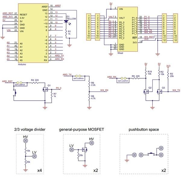
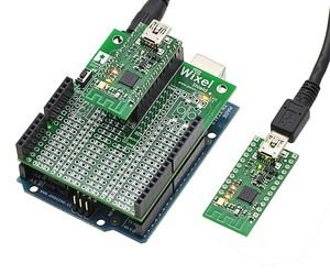
Wixel Socket
The shield relies upon a pair of Wixels for its wireless connection. The shield’s Wixel socket allows the Wixel to be removed and used for other applications.
1.c. Arduino Pin Usage
The Wixel shield connects to these pins on the Arduino:
- Pin 0 (RX)
- Pin 1 (TX)
- Pin 13 (user LED)
- RESET
- 5V
- GND
The shield uses the Arduino’s 5 V regulator to power the socketed Wixel. It is safe to use this shield in conjunction with other Arduino shields or electronics that also use these pins, though such electronics could potentially interfere with the operation of the Wixel shield (and vice versa). For details about the connections, see the Wixel shield for Arduino schematic in Section 1.d.
For more detail: Pololu Wixel Shield for Arduino User’s Guide