The physical interface will consist of a 3×3 grid of push buttons that will correspond to a 3×3 grid of images in the Processing program. Instead of a creating a 2D array of variables to correspond to the buttons’ postions in the grid, each location in the grid will be assigned a number. Each push button will represent the corresponding number in the image grid. For the purposes of prototyping, a 5-button system will be used, as the design of the system is scalable.
List of components:
- 5 x momentary push button
- 5 x 10kΩ resistor
- Arduino Uno
- Solderless breadboard
- hookup wires
- each pushbutton is connected to power (5V),
- each push button is connected in series with a 10kΩ pulldown resistor, which is in turn connected to ground,
- each pushbutton is connected at the junction point between the button and the resistor to digital pins 2-6.
Each push button is connected to the 5V power supply. The other side of the pushbutton is connected to a 10KΩ pulldown resistor, which in turn is connected to ground. The circuit is connected to the digital pin at the junction point between the pushbutton and the resistor. The resistor provides the pushbutton with a reference to ground and helps provide more stable readings.
State change detection allows us to determine when the button’s state has changed from high to low, indicating that it has been pressed. To do this, we create a variable to store the button’s previous state. A global variable is created for each button’s state, then initialised in setup(). Each button makes use of a conditional statement that compares the button’s previous state to its current one. If the states are different, it means the button has been pressed. By considering the fact that the Arduino and Processing will be communicating serially, it makes sense from an efficiency standpoint to send as little data as possible. In light of this, we created an int variable called “buttonValue” that stores the value the button that was pressed most recently. This is done using a collection of conditional statements. See code below:
if (buttonState1 != previousButtonState1){
if(buttonState1 == HIGH){
buttonValue = 1;
}
}
if (buttonState2 != previousButtonState2){
if(buttonState2 == HIGH){
buttonValue = 2;
}
}
if (buttonState3 != previousButtonState3){
if(buttonState3 == HIGH){
buttonValue = 3;
}
}
if (buttonState4 != previousButtonState4){
if(buttonState4 == HIGH){
buttonValue = 4;
}
}
if (buttonState5 != previousButtonState5){
if(buttonState5 == HIGH){
buttonValue = 5;
}
}
By doing this, we only need to send one piece of information to the processing program – the data stored in the buttonValue variable, ie. a number between 1 and 5. Each button’s previousState variable is set to its current value, which will be used to evaluate against in the next loop() cycle.
The code for Arduino sketch is available here.
Prototyping the swipe gesture controller
List of components:
- 2 x Infrared LED emitter (tinted package)
- infrared LED detector (clear package)
- Red LED
- 2 x 220Ω resistors
- 1 x 1.5kΩ resistor
- IR emitter LEDS connected in parallel to digitalPin 2 with 220Ω resistor.
- IR receiver connected to A0 with 1.5kΩ resistor.
- Red LED connected to digitalPin 13 with 220Ω resistor.
We decided to make a swiping gesture the main navigation mode as it’s already familiar to all smartphone users and thus all instagram users. We created a simple proximity sensor, using infrared LEDs and an infrared LED photoresistor (which are available as a pair from RadioShack). The Infrared light emitted by the LEDs bounces off of nearby objects and is decected by the IR detector. The proximity of the object is determined by the amount of light being received by the sensor. The user is provided with visual feedback in the form of an illuminated red LED to confirm that the action was performed successfully.
A portion of the code was informed by a project on instructables by Ricardo Uvino, who describes how to make a simple proximity sensor. One of the problems with using an IR detector is that they pickup not only the IR light emitted by the IR LEDs, but the ambient environmental IR light. His code includes a very clever function (See below) that takes this into account by storing a value when the IR LEDs are LOW, which represent the ambient IR light, and comparing this to the values attained when an object is detected. An average value is then generated by dividing these accumulated values by the number of samples.
int readIR(int times){
for(int x=0;x<times;x++){
// turning the IR LEDs off to gauge ambient IR light from environment
digitalWrite(IRemitter,LOW);
// minimum delay necessary to read values
delay(1);
// storing IR coming from the ambient
ambientIR = analogRead(IRpin);
// turning the IR LEDs on to read the IR coming from the obstacle
digitalWrite(IRemitter,HIGH);
// minimum delay necessary to read values
delay(1);
// storing IR coming from the obstacle
obstacleIR = analogRead(IRpin);
// calculating changes in IR values and storing it for future average
value[x] = ambientIR-obstacleIR;
}
// calculating the average based on the “accuracy”
for(int x=0;x<times;x++){
distance+=value[x];
}
return(distance/times); // return the final value
Despite having the ability to gauge the distance between the user’s hand and the sensor, this functionality would be superfluous to our needs, so we introduced a threshold value to simply switch a boolean variable from false to true when the presence of the user’s hand is detected. This threshold will have to be determined in each new environment using the Serial monitor window, by uncommenting the line //Serial.println(sensorValue); We created the variables ‘sensorState’ and ‘previousSensorState’ so that we could compare the two to detect a state change, in the same way you would a push button. If the conditional statement evaluates to true, the boolean variable ‘swipe’ is set to ‘true’. An additional if() statement will be used to evaluate this boolean before sending data serially to processing.
Combining the functionality
The pin-layout and list of components are as above.
The main challenge in combining the functionality of the button grid and the gesture detection is sending the right amount of data, at the right time, serially to processing. Once the combined sensor circuit has been constructed (see schematic below), the first step in the process is calibrating the IR sensor threshold for the given light conditions.
To calibrate the IR sensor, we use the serial monitor to check the analog reading when no object is detected and compare that to the range of values when an object is detected. To do this, we uncomment the following lines of code from the sketch: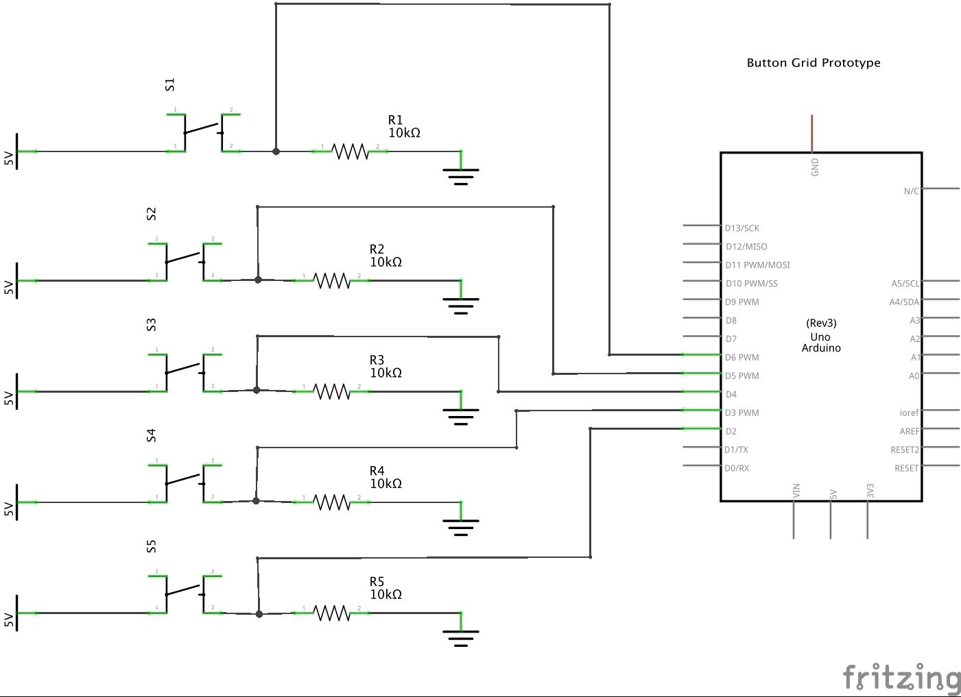 Serial.print(“Calibrating sensor value: “);
Serial.println(sensorValue);
These commands overwrite the serial.print instructions inside the serial.available() conditional statement and display a constant stream of data that can be used to determine the threshold. From the video, we can see that when no object is detected, the sensorValue sits at around 3 and has an upper range of around 20. Assuming that light conditions will not change too much during use, we can set a relatively low threshold value to ensure an accurate and sensitive sensor. This is done outside of setup(), by creating a global variable:
int sensorThreshold = 5; //set threshold value to detect presence of user’s hand
Once the threshold has been set, we can comment out the lines of Serial.print() calibration code and begin combining the data. As mentioned in the previous section, minimizing the amount of information sent to Processing improves the efficiency of the communication. Earlier tests yielded erratic and somewhat unstable readings. To rectify this, we changed over to the handshaking (or call-and-response) method of communication. In addition to this, we created an outgoing serial buffer of sorts, to ensure that the necessary information was sent only at the point when it was requested. See the portion of code below:
For more detail: PhysComp: Mid-term Project – Instagram TUI – prototyping the interactive elements using Arduino